5-1SectionConnecting to the Host’s RS-422A/485 Port
89
Wiring to one of the following Serial Communications Boards/Units
• CS-series CS1G/H(-H) Serial Communications Board
• CJ-series CJ1G Serial Communications Unit
• C-series C200HX/HG/HE(-Z)E Serial Communications Board
• CQM1H Serial Communications Board
Applicable Units:
CS1G-CPU42-E(V1) CS1G-CPU43-E(V1)
CS1G-CPU44-E(V1) CS1G-CPU45-E(V1)
CS1H-CPU63-E(V1) CS1H-CPU64-E(V1)
CS1H-CPU65-E(V1) CS1H-CPU66-E(V1)
CS1H-CPU67-E(V1)
CS1G-CPU42H CS1G-CPU43H
CS1G-CPU44H CS1G-CPU45H
CS1H-CPU63H CS1H-CPU64H
CS1H-CPU65H CS1H-CPU66H
CS1H-CPU67H
CJ1W-SCU41 (communication port 1)
C200HE-CPU32-(Z)E C200HE-CPU42-(Z)E
C200HG-CPU33-(Z)E C200HG-CPU43-(Z)E
C200HG-CPU53-(Z)E C200HG-CPU63-(Z)E
C200HX-CPU34-(Z)E C200HX-CPU44-(Z)E
C200HX-CPU54-(Z)E C200HX-CPU64-(Z)E
C200HX-CPU65-ZE C200HX-CPU85-ZE
CQM1H-CPU51 CQM1H-CPU61
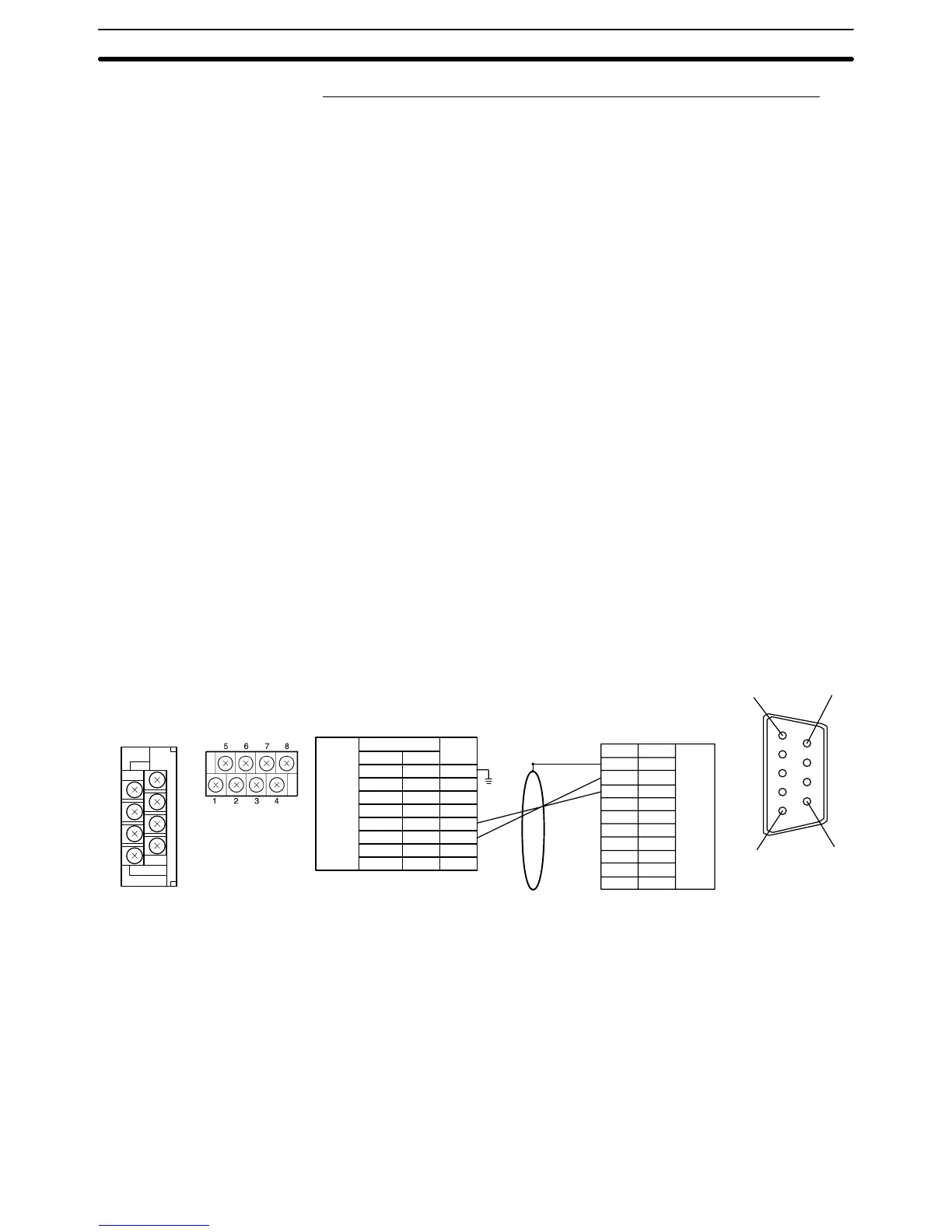
6
5
9
1
RS-422A
connector
Pin number
Connector
hood
1
2
3
4
5
6
7
8
9
Abbreviation
FG
SDA
SDB
–
–
–
RDA
–
RDB
–
(9-pin
type)
PC (CPU Unit)
NS-AL002NT-AL001
Pin number Abbreviation
F. Ground
SG
SDB
SDA
RDB
RDA
CSB
CSA
DIP Switch Settings
NT-AL001: Pins 1 to 4 and 6 ON
Pins 5 OFF
NS-AL002: All pins ON
Link Adapter
RS-422A
terminal
block
NT-AL001
1
2
3
4
5
6
7
8
NS-AL002
1
---
3
7
2
6
---
---
7
5
3
1
8
6
4
2
Shield
To avoid an FG ground loop, do not connect the functional ground of the Link
Adapter to the shielding of the RS-485 cable.
5-1-4 1:N Connection to the Host’s RS-422A Port
This
section explains how to connect the RS-232C ports of two or more NT21s
with the host’s RS-485 port through Link Adapters.
Link Adapters (NT-AL001 or NS-AL002) are required to convert communica-
tions methods between the RS-232C and RS-422A formats.