2-2SectionNames and Functions of Parts
14
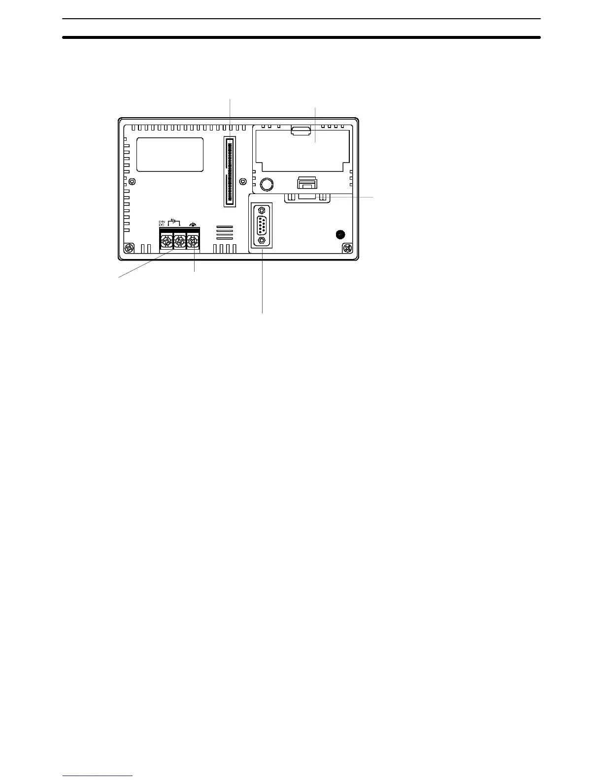
Rear
V
iew
Battery cover
There is a battery holder beneath this cover
. The
battery is optional (sold separately) and is not
installed when the NT21 is shipped.
Expansion interface connector
When using an Expansion Interface Unit
such as a Memory Unit, connect it here.
GR terminal
Grounding terminal to
prevent malfunction
due to noise.
Power input terminals
Connect the power to the
NT21 at these terminals.
Serial port A connector
Connect the cable for connection to the host or NT Support
T
ool here. A bar code reader can also be connected here.
This is a 9-pin connector for RS-232C only
.
Serial port B connector
Connect the cable for connection to the
host here. An NS-AL002 Link Adapter can
be connected directly to this port. This is a
9-pin connector for RS-232C only
.
Note Before
turning the power ON/OFF
, confirm system safety
, otherwise the
system
may operate unpredictably.