6
7
8
9
1
2
3
4
5
3-2SectionConnecting Link Adapters
27
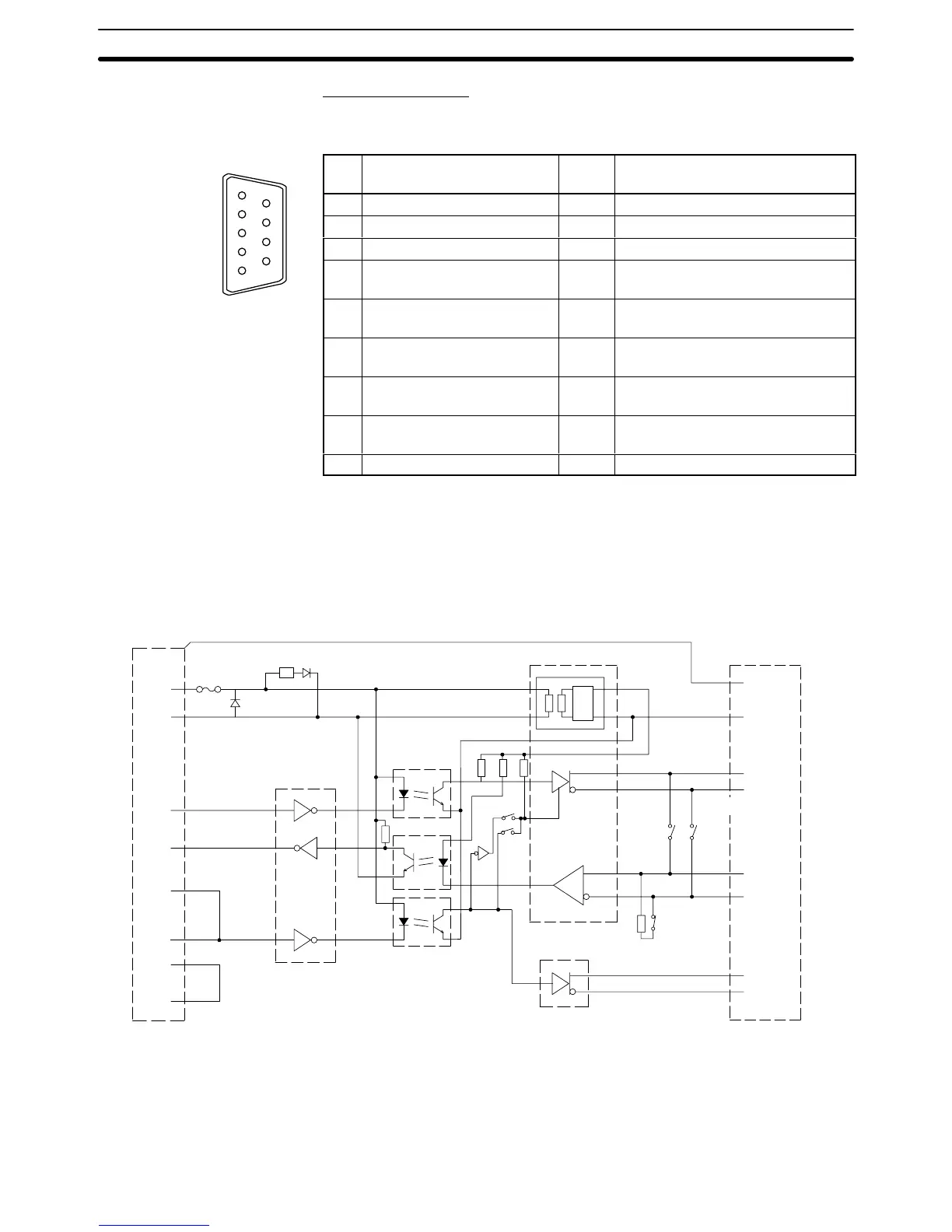
RS-232C Connector
The
connector hood
is connected to the RS-422A terminal block’
s frame ground
terminal.
Pin Signal name Code
Signal direction
(RS-232C Device ⇔ Link Adapter)
1 Not used --- ---
2 Send data SD RS-232C Device ← Link Adapter
3 Receive data RD RS-232C Device → Link Adapter
4 Request to send
(shorted to CS internally)
RS RS-232C Device ← Link Adapter
5 Clear to send
(shorted to RS internally)
CS RS-232C Device → Link Adapter
6 +5 V (150 mA) input for Link
Adapter
+5 V RS-232C Device → Link Adapter
7 Data set ready
(shorted to ER internally)
DR RS-232C Device → Link Adapter
8 Data terminal ready
(shorted to DR internally)
ER RS-232C Device ← Link Adapter
9 Signal ground SG ---
The
following diagram shows the internal block diagram of the NT
-AL001-E Link
Adapter. Refer to this diagram only when wiring custom cables or connecting
devices with special interfaces.
SW1-6
Terminating
resistance
R
R
D-SUB
9-pin
Case
+5 V
SG
SD
RD
RS
CS
DR
ER
6
9
2
3
4
5
7
8
POWER
Indicator
RS-232C
Dr/Rec
RS-422A/485 Dr/Rec
DC-DC
IS_5 V
IS_0 V
FG
1
2
3
4
6
5
7
8
SW1-5
SW1-4
SG
SDB
SDA
RDB
RDA
CSB
CSA
SW1-2
RS-422A Dr
SW1-3
RS-232C side
Fuse
Convertor
RS-422A/485 side
8 terminal block
Photocoupler
2-wire/
4-wire
RR
R
R
LL REG
When
using RS-422A or RS-485 cables for long-distance communications, do
not
ground the shield at both ends of the communications line because large cur
-
rents can flow through the shield due to the difference in potential at the two
Block Diagram
RS-422A/485 Cable
Shield Connections