4-1SectionConnecting to the RS-232C Port at the Host
53
Port connecting to PT PC Setup
RS-232C port (D-Sub 9-pin) of CPM2C-CN111 Built-in RS-232C port settings
Peripheral port of CPM2C-CN111 Peripheral port settings
RS-232C port (D-Sub 9-pin) of CS1W-CN118 Built-in RS-232C port settings
Peripheral port of CS1W-CN114 Peripheral port settings
Peripheral
port
RS-232C port
(D-Sub 9-pin, female)
CPM2C-CN111
CPM2C
RS-232C port
(D-Sub 9-pin, female)
CS1W-CN118
CPM2C
Peripheral port
CS1W-CN114
CPM2C
Setting the DIP Switches on the Front of a C200HX/HG/HE(-Z)E, CQM1,
CQM1H
When using a C200HX/HG/HE(-Z)E, CQM1, or CQM1H, the DIP switches on
the
front panel must be set as shown below in order to make the settings in the
PC Setup (data memory) effective.
C200HX/HG/HE(-Z)E
CQM1 CQM1H
RS-232C
port communication condition setting
Set pin 5 to OFF to make the settings made in
PC Setup ef
fective.
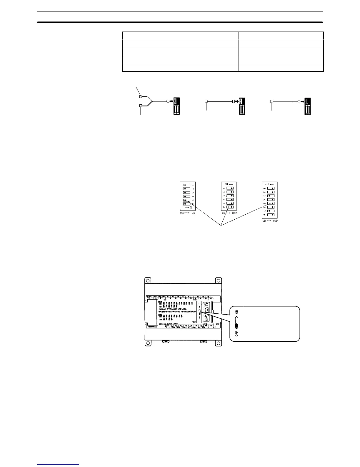
Setting the Switches of a CPM2A
When using a CPM2A, the switches on the front panel must be set as shown
below in order to make the PC Setup settings effective.
Set
the Communications
switch to OFF (down
position).