5-1SectionConnecting to the Host’s RS-422A/485 Port
77
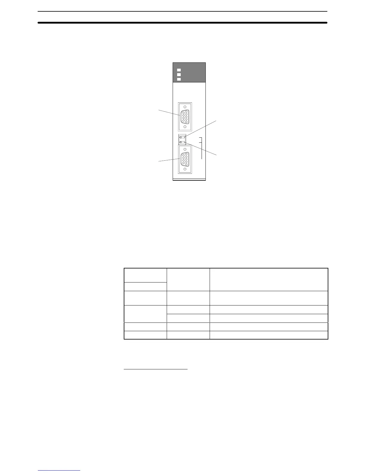
Setting the Front Switches
Port
1
RS-232C
Port 2
RS-422A/485
Terminal resistance setting switch (TERM)
Set to ON (Terminal resistance is present.) (right side)
Two-wire/four-wire changeover switch (WIRE)
4 (4-wire) (right side)
PORT1
ON
TERM
4 WIRE
OFF
2
PORT2
(RS422/
RS485)
RDY
COMM1
COMM2
SCB41
Allocated DM Area Settings for CPU Unit
Settings
are written from the Programming Device (a Programming Console or
CX-Programmer)
directly into
the allocated DM Area settings (PC Setup) of the
CPU Unit. After the settings are written, they become effective by turning the
power
ON, restarting the Unit, restarting the communication port, or executing
the STUP instruction.
The
following table shows the words allocated in the DM Area and the settings.
Allocated DM
word
Value Settin
DM32010 8000 Host Link mode, 2 stop bits, data length 7 bits,
even parity,
DM32011 0000 Baud rate 9,600 bps.
0007 Baud rate 19,200 bps.
DM32012 0000 Transmit delay time 0 ms.
DM32013 0000 No CTS control Unit No.0 for Host Link
Using the 1:1 NT Link Method
Compatible Host Units
Some
models and series of
OMRON PCs have the RS-422A 1:1 NT Link func
-
tion built in.
• The
C200HX/HG/HE(-Z)E CPU Units
can be connected by the RS-422A 1:1
NT Link method by installing a Serial Communications Board.
• The
CQM1H CPU Units can be connected by the RS-422A 1:1 NT Link method
by installing a Serial Communications Board.
Check
the model and series of the PC and the type of installed Serial Commu
-
nications Board before making connections.