5-1SectionConnecting to the Host’s RS-422A/485 Port
79
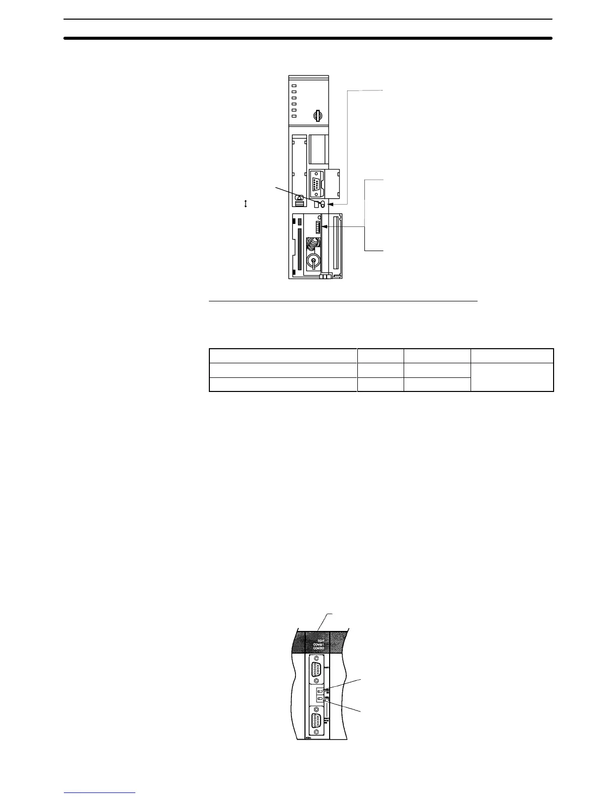
Setting the Front Switches
@
Host Link communication method selection
(selector switch)
Set this to RS-422A.
@
T
erminator setting (pin 6)
Set this switch to ON.
(Set terminator ON.)
I/O port selector switch
RS-422A
RS-232C
@
Communications type setting (pin 3)
Set this switch to ON.
(for communication by NT link)
Connecting to a C-series C200HX/HG/HE(-Z)E or CQM1H
PC Setup Settings
Write
the PC
Setup (data memory) settings directly from a Programming Device
(e.g., CX-Programmer) in accordance with the host model.
Host Model Word Writing Value Setting
Port A of C200HX/HG/HE(-Z)E
*1
DM6555 4000 Use 1:1 NT Link
Port 2 of CQM1H
*2
DM6550 4000
*1 RS-422A port of the Serial Communications Board
*2 RS-422A port of the Serial Communications Board
For
details on operations relating to the PC Setup, refer to
the manual for the PC
you are using.
Setting the DIP Switches on a C200HX/HG/HE(-Z)E Serial Communica-
tions Board
Set the switches on a C200HX/HG/HE(-Z)E Serial Communications Board as
follows.
Switch 1: Set to 4 (4-wire, for RS-422A)
Switch 2: Set to ON for terminator ON (terminating resistance applied)
Setting Switches on a CQM1H Serial Communications Board
Set the switches on a CQM1H Serial Communications Board as follows.
Wire selection (WIRE): Set to 4 (4-wire, for RS-422A)
Terminator (TERM): Set to ON for termination ON.
Serial
Communications Board
(Inner Board slot 1)
T
erminator Switch (TERM)
Set to ON (right side).
Wire Selection Switch (WIRE)
Set to 4 (right side).