5-1SectionConnecting to the Host’s RS-422A/485 Port
81
communications
and set the terminator switch to enable or disable the terminat
-
ing resistance.
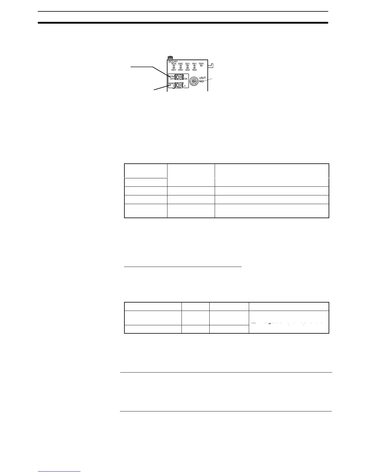
Unit
number switch
Set the a unique unit number between
0 and F so that there is not a conflict
with the numbers used in other Units.
Terminal resistance switch (TERM)
Set to ON (Terminal resistance is present.)
Communications mode switch (WIRE)
For RS-422A: 4 (4-wire)
For RS-485: 2 (2-wire)
Allocated DM Area Settings for CPU Unit
Settings
are written from the Programming Device (a Programming Console or
CX-Programmer)
directly into
the allocated DM Area settings (PC Setup) of the
CPU
Unit.
After settings are written, they become ef
fective by turning the power
ON, restarting the Unit, restarting the communication port, or executing the
STUP instruction.
The
following table shows the words allocated in the DM Area and the settings.
Allocated DM
word
Writin
DM32000 8200 1:N NT Link mode
DM32001
0000 to 0009
(*1)
Communications baud rate (standard)
DM32006 000j j = The largest model number of the con-
nected PTs (0 to 7)
*1 Set any value between 0000 and 0009 Hex for the communications baud rate.
The same baud rate will be used regardless of the value as long as it is between
0000 and 0009 Hex.
For
example, when connecting PT
s with model
numbers 3, 4, 5, and 6 to port 1,
set
DM 32000 to 8200 Hex, DM 32001 to 0000 Hex, and DM 32006
to 0006 Hex.
C-series C200HX/HG/HE(-Z)E and CQM1H
PC Setup Settings
Write the communication conditions directly into the PC Setup (data memory)
using a Programming Device (e.g., CX-Programmer).
Make the setting indicated in the word shown below.
Host Model Word Writing Value Setting
Port A of a C200HX/
HG/HE(-Z)E
*1
DM6555 5j00
Use 1:N NT Link
j = largest unit number of the
Port 2 of a CQM1H
*2
DM6550 5j00
connected PTs (1 to 7)
*3
*1 The Serial Communications Board’s RS-422A/485 port
*2 The Serial Communications Board’s RS-422A/485 port
*3 When using C200HE(-Z)E, the maximum PT unit number is 3.
For
details on setting the PC Setup settings, refer to the PC’
s operation manual.
Reference: S There
are no Serial Communications Boards for the C200HX/HG/HE(-Z)E in
which port B is the RS-422A/485 port.
S There
are no Serial Communications Boards for
the CQM1H in which port 1 is
the RS-422A/485 port.
Setting the DIP Switches on a C200HX/HG/HE(-Z)E Serial Communica-
tions Board
Set the switches on a C200HX/HG/HE(-Z)E Serial Communications Board as
follows.