DM32010 8200 1:N NT Link mode
DM32011
0000 to 0009
(*1)
Communications baud rate (standard)
DM32016 000j j = The largest model number of the con-
nected PTs (0 to 7)
*1 Set any value between 0000 and 0009 Hex for the communications baud rate.
The same baud rate will be used regardless of the value as long as it is between
0000 and 0009 Hex.
For
example, when connecting PT
s with model
numbers 3, 4, 5, and 6 to port 2,
set
DM 32010 to 8200 Hex, DM 3201
1 to 0000
Hex, and DM 32016 to 0006 Hex.
Using the High-speed 1:N NT Link Method
Compatible Host Units
The OMRON PCs that can be connected using the high-speed RS-422A/485
1:N
NT Link are the CS-series (CS1G/H and CS1G/H-H), CJ-series CJ1G mod
-
els
only
. With the CS-series, a CS1W
-SCB41-E Serial Communications Board
must
be used. With the CJ-series, a CJ1W
-SCU41 Serial Communications Unit
must be
used. (If a Serial Communications Board is used, even CS-series Units
without the “-V1” suffix can be connected via high-speed 1:N NT Link.)
Be sure to check the model number of the PC and Board/Unit before trying to
establish the high-speed 1:N NT Link.
The
following table
shows which Units can be connected as hosts to the NT21
with the high-speed 1:N NT Link through the RS-422A/RS-485 port.
PC Series
PCs supporting direct
connection to the CPU Unit
PCs supporting connection through a
Serial Communications Board/Unit
Connectable
models
CS Series ---
CS1G-CPU42/43/44/45-E(V1)
(*1)
CS1H-CPU63/64/65/66/67-E(V1)
(*1)
CS1G-CPU42H/43H/44H/45H
(*1)
CS1H-CPU63H/64H/65H/66H/67H
(*1)
CS1G
CS1H
CS1G-H
CS1H-H
CJ Series --- CJ1G-CPU44/45
(*2)
CJ1G
*1 A CS1W-SCB41 Serial Communications Board is required.
*2 A CJ1W-SCU41 Serial Communications Unit is required.
Settings at the Host
Connecting to a CJ-series Serial Communications Unit
CJ-series: CJ1W-SCU41 (Port 1 is an RS-422A/485 port.)
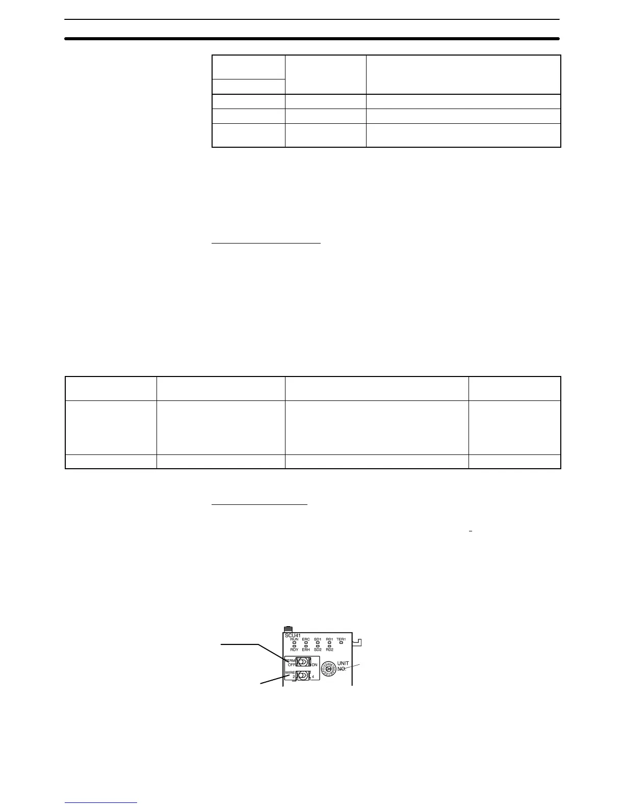
Setting the Front Switches
Set
the unit number of the Serial Communications Unit with the rotary switch on
the
front of the Unit. Set the unit number with a flat blade screwdriver
. Also, set
the
communications mode switch to select
2-wire (RS-485) or 4-wire (RS-422A)
communications
and set the terminator switch to enable or disable the terminat
-
ing resistance.
Unit
number switch
Set the a unique unit number between
0 and F so that it will not duplicate the
numbers used in other units.
Terminal resistance switch (TERM)
Set to ON (Terminal resistance is present.)
Communications mode switch (WIRE)
For RS-422A: 4 (4-wire)
For RS-485: 2 (2-wire)
CPU Unit Allocated DM Area Settings
Setting
is written from the Programming Device
(a Programming Console or CX-
Programmer)
directly into the
allocated DM Area settings (PC Setup) of the CPU