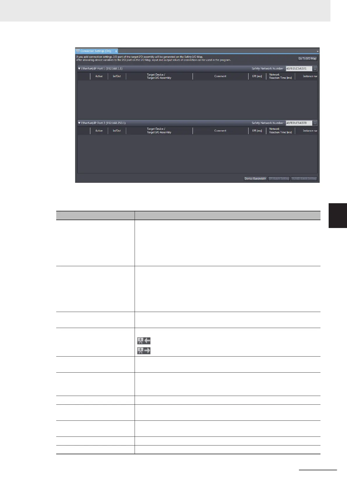
The Connection Settings (Originator) Tab Page consists of the items shown in the following ta-
ble.
Item Description
EtherNet/IP Port 1 Settings of CIP Safety connections via the built-in EtherNet/IP port 1 are list-
ed.
Safety Network Number: Specifies the SNN for the EtherNet/IP network for
which the port 1 is connected
Connection list: Connections grouped together by each target device are list-
ed.
EtherNet/IP Port 2 Settings of CIP Safety connections via the built-in EtherNet/IP port 2 are list-
ed.
Safety Network Number: Specifies the SNN for the EtherNet/IP network for
which the port 2 is connected
Connection list: Connections grouped together by each target device are list-
ed.
Target Device IP address, Unit number, and device name are displayed for the target device
with which a CIP Safety connection is to be opened.
In/Out Shows the data direction of each connection.
: In - Data to be received from the target device
: Out - Data to be sent to the target device
Target I/O Assembly I/O Assembly name of the target device with which a connection is to be
opened is displayed.
Active Enable/disable each connection.
Selected: Connection is active.
Not selected: Connection is inactive.
EPI [ms] Specifies the Expected Packet Interval (data update cycle) in ms.
Network Reaction Time [ms] Displays the value of the Network Reaction Time in ms. This is used in calcu-
lating the safety reaction time.
Instance name Name of the instance being managed in the program. Connection status can
be checked if the connection is registered in the W
atch T
ab Page.
Go To I/O Map Button Click this button to open the I/O Map Tab Page.
Device Bandwidth Button Click this button to show bandwidth usage of originator connection.
5 System Configuration and Setup
5 - 15
NX-series Safety Control Unit User's Manual (Z930)
5-4 Setting Up the Safety Process Data Communications
5
5-4-2 Setting Up the CIP Safety Communications
 Loading...


