Item Specification
External con-
nection termi-
nals
Screwless clamping terminal block (8 terminals)
Indicators [TS] indicator, [FS] indicator, [OUT] indicator, [OUT ERR] indicator
[OUT] indicator
[O
UT ERR] indicator
Safety output
ON residual
voltage
1.2 V max. (between IOV and all output terminals)
Safety output
OFF residual
voltage
2 V max. (between IOG and all output terminals)
Safety output
leakage cur-
rent
0.1 mA max.
Dimensions
(mm)
12 × 100 × 71 (W × H × D)
Isolation meth-
od
Photocoupler isolation
Insulation re-
sistance
20 MΩ min. between isolated circuits (at 100 VDC)
Dielectric
strength
510 VAC between isolated circuits for 1 minute at a leakage current of 5 mA max.
I/O power sup-
ply method
Power supplied from the NX bus
Current ca-
pacity of I/O
power supply
terminals
IOG: 2 A/terminal max.
NX Unit power
consumption
• Connected to a CPU UNIT or a Communication Control Unit
1.05 W max.
• Connected to a Communications Coupler Unit
0.70 W max.
Current con-
sumption from
I/O power sup-
ply
40 mA max.
Weight 65 g max.
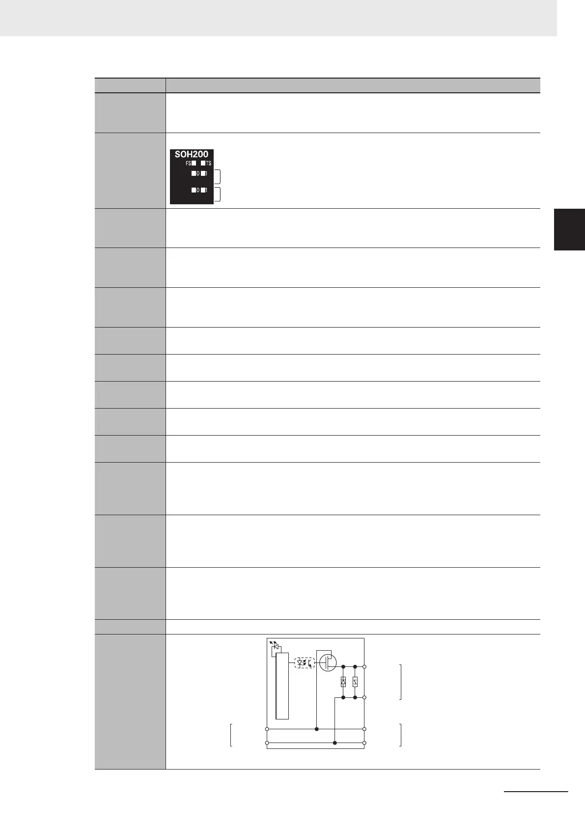
Circuit layout
I/O
power
supply -
NX bus connector
(right)
Internal Circuits
So0–1
Terminal block
IOG
I/O
power
supply +
I/O
power
supply -
I/O
power
supply +
NX bus connector
(left)
2 Specifications
2 - 31
NX-series Safety Control Unit User's Manual (Z930)
2-3 Safety Output Unit
2
2-3-1 Models and Specifications
 Loading...


