S82J
S82J
20
Generating Output Voltage (±)
An output of ± can be generated by using two Power Supplies as
shown below, because the Power Supply produces a floating out-
put.
INPUT
INPUT
+V
–V
+V
–V
Load
Load
+V
0 V
–V
If
operation amplifiers as loads are connected in series, connect a
diode between the positive and negative output terminals of each
Switching
Power Supplies as shown in the illustration below
. With
-
out these diodes, the Power Supplies may not start when power is
turned
on, possibly damaging
internal circuits over a period of time.
Use
Schottky barrier diodes with a low forward voltage (V
F
). Other
types
of diodes will not be ef
fective.
Guidelines for the dielectric strength and current of the diodes
are
as follows:
Dielectric strength: At least twice the rated output voltage of the
Power
Supply
Forward current: At least twice the rated output current
No diodes are required for models that allow series operation.
INPUT
+ V
– V
+ V
– V
INPUT
D
1
D
2
Load
Load
Load
Series Operation
Only
models with power ratings of 50/100/150/300/600 W allow se
-
ries
operation.
As shown in the following diagram, the output voltage from each
Switching
Power Supply can be added.
INPUT
+V
–V
+V
–V
INPUT
Load
D
1
D
2
With
the S82J-050
jjjj
or S82J-10024
jj
, if the load is shorted
a
reverse voltage may
result in the Power Supply causing deteriora
-
tion
and damage. It is recommended that diodes are connected as
shown
in the previous diagram (D
1
, D
2
).
Parallel Operation
Only 300- and 600-W models can be in parallel operation. Do not
operate any other models in parallel. The output of the models in
parallel
operation is a maximum of 80% of the rated output.
Set
the parallel operation selector to P
ARALLEL if the Units are in
parallel
operation and make sure that the thickness and the
length
of all wires connected to the load are the same to ensure that the
wires
will have no voltage drop dif
ferences.
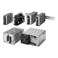
Fan Replacement
The
service life of the fan is approximately 50,000 hours (at 25
°C).
The
service life varies, however
, depending on
the ambient temper
-
ature
or other surrounding environmental conditions
such as dust.
As a preventive maintenance measure, replace the fan within two
years
if it is used at an ambient temperature of 40
°C.
Fans are available as replacements.
Model: S82Y
-JFAN
Fan Set:
Fan (above), four M4 x 35 sems screws, instruction sheet, and
packing case
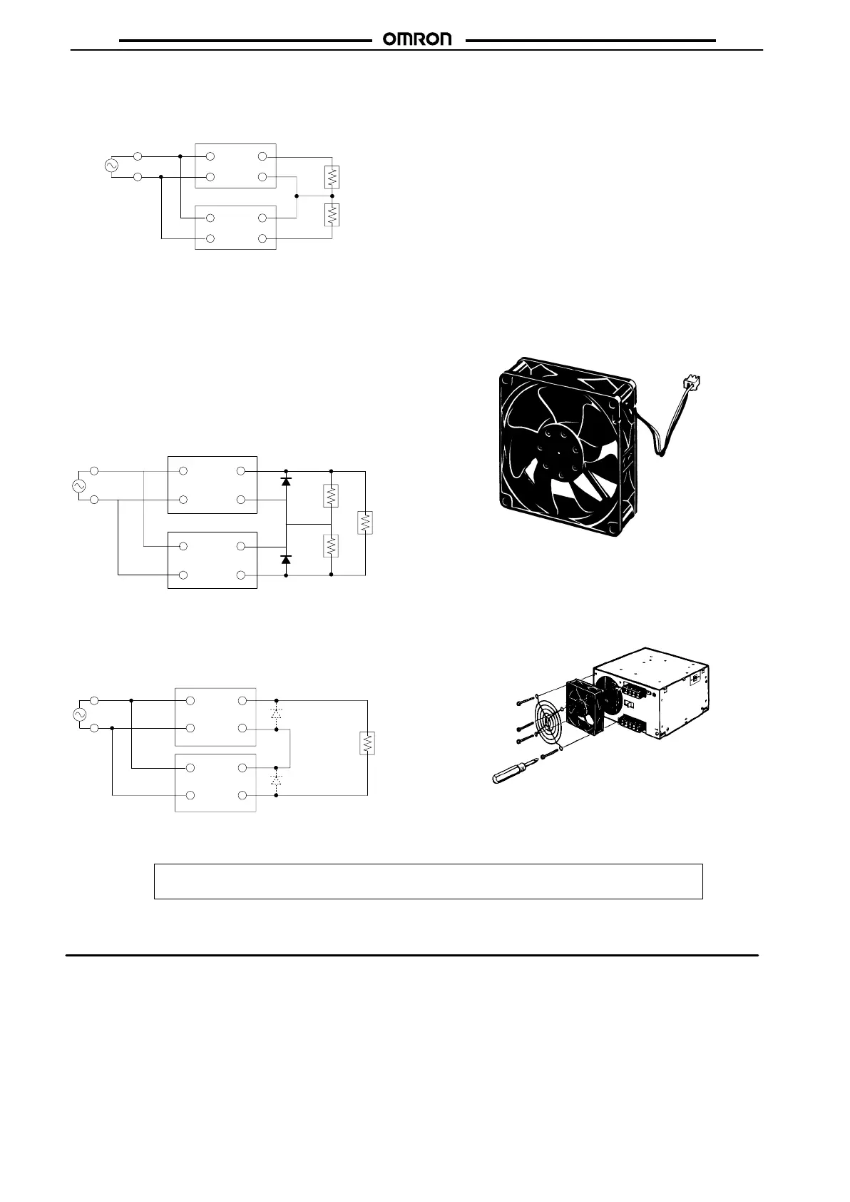
Replace the fan as shown in the following illustration.
OMRON Corporation
Industrial
Automation Company
Measuring
and
Supervisory Controls Department
Shiokoji
Horikawa, Shimogyo-ku,
Kyoto, 600-8530 Japan
Tel: (81)75-344-7108/Fax: (81)75-344-7189
ALL DIMENSIONS SHOWN ARE IN MILLIMETERS.
To
convert millimeters into inches, multiply by 0.03937. T
o convert grams into ounces, multiply by 0.03527.
Cat. No. M047-E1-6 In the interest of product improvement, specifications are subject to change without notice.
Printed
in Japan
0301-2M (A)
 Loading...