14 Switch Mode Power Supply S8VM
Construction and Nomenclature (300-W, 600-W, 1,500-W Models)
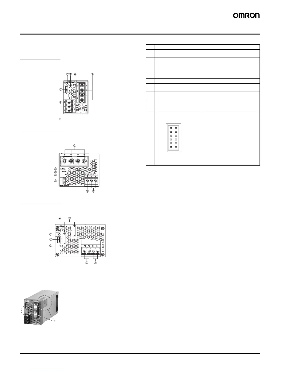
■ Nomenclature
300-W Models
S8VM-300@@C
600-W Models
S8VM-600@@C
1,500-W Model
S8VM-15224C
■ Output Color Label
This color label identifies the output voltage by color.
Note: A 300-W model is shown above. The label is in a different place
on 600-W models and 1,500-W model.
Note: 1. The fuse is located on the (L) side. It is NOT user-replace-
able.
2. Protective earthing connection is the panel mounting hole of
the metal case. (A protective earthing connection stipulated
in safety standards is used. Connect the ground complete-
ly).
Ground terminal: M4 (Depth: 6 mm max.)/Ground wire:
AWG 18
3. The enclosed standard connector for signal I/O is mounted
to CN when S8VM is shipped. The enclosed signal I/O con-
nector shorts between 1 and 2, between 3 and 4, and be-
tween 7 and 8.
Do not connect a load to the output voltage monitor termi-
nals (+V, -V).
Color label identifying output voltage
Green: 5 V
Blue: 12 V
Yellow: 15 V
White: 24 V
No. Name Function
1 AC input terminal (L), (N) Connect the input lines to these terminals.
(See note 1.)
2 PE terminal: Protective earth-
ing terminal
(S8VM-300@@C/S8VM-
600@@C)
FG terminal: Frame ground ter-
minal (S8VM-15224C)
Connect the ground line to this terminal.
(See note 2.)
3 DC output terminals (
−V), (+V) Connect the load lines to these terminals.
4 Output indicator (DC ON:
Green)
Lights (green) while a direct current (DC)
output is ON.
5 Output voltage adjuster
(V.ADJ)
Use to adjust the voltage.
6 Power failure alarm indicator
(PF: Red)
Lights when the output voltage decreases,
the fan stops, and the system is on stand-
by using the remote control function.
7 Signal I/O connector (See note
3.)
1: DC output monitor pin (+V)
2: Remote sensing pin (+S)
3: DC output monitor pin (-V)
4: Remote sensing pin (-S)
5: Current balance pin (CB)
6: Signal ground pin for current balance
(CBG)
7: Remote control pin (+RC)
8: Remote control pin (-RC)
9: No connect
10: No connect
11: Power failure alarm output pin (PF-C)
(collector)
12: Power failure alarm output pin (PF-E)
(emitter)
1
3
5
7
9
11
2
4
6
8
10
12
CN