8 Switch Mode Power Supply S8VM
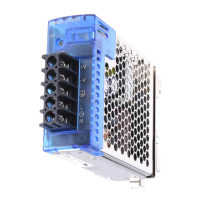
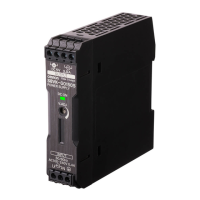
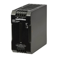
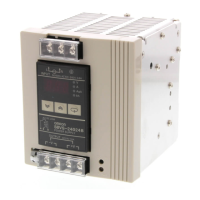
Construction and Nomenclature (15-W, 30-W, 50-W, 100-W, 150-W Models)
■ Nomenclature
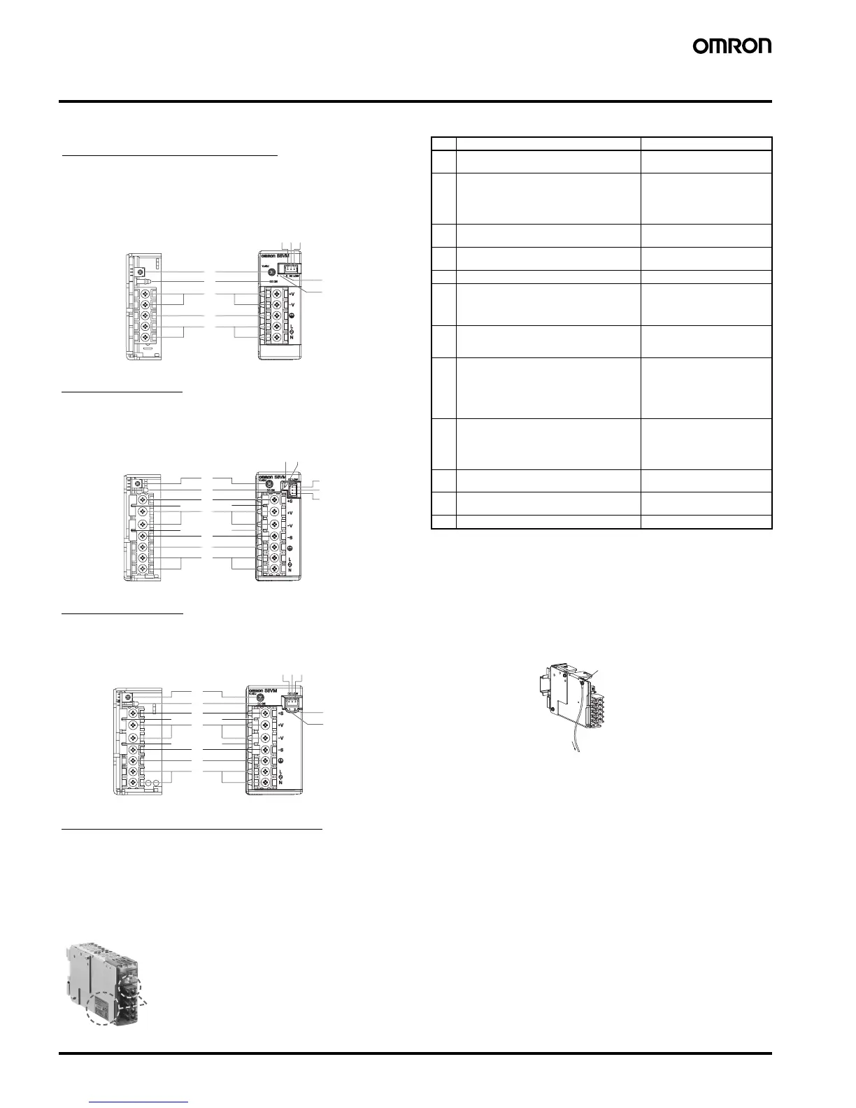
Note: 1. The fuse is located on the (L) side. It is NOT user-replace-
able.
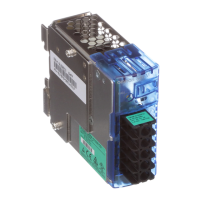
2. If mounting is performed using a DIN Rail, the protective
earthing connection is the panel mounting hole shown in the
figure below.
(A protective earthing connection stipulated in safety stan-
dards is used. Connect the ground completely (S8VM-
@@@@@D only)).
Ground terminal: M3 (Depth: 8 mm max.)/Ground wire:
AWG 18
3. S8VM-@@@24A@/P@ only
4. S8VM-05024A@/P@, S8VM-10024A@/P@, S8VM-
15024A@/P@ only. Housing and terminals of the connector
for undervoltage detection output are also provided. For de-
tails, refer to Undervoltage Alarm Output Connector Har-
ness Manufacture Method on page 33 under Safety
Precautions.
5. When not using the remote sensing function, leave the short
bar in the same state as when shipped.
6. A@ models: Common terminal (emitter)
P@ models: Common terminal (collector)
■ Output Color Label
5
4
3
2
1
6
7
8910
12
12
1
2
11
8
9
1
3
11
4
5
67
12
12
1
2
11
3
11
4
5
12
12
6
7
8910
12
12
15-W, 30-W, 50-W Models
Open-frame Models Covered Models
S8VM-015@@/S8VM-015@@D
S8VM-030@@/S8VM-030@@D
S8VM-050@@/S8VM-050@@D
100-W Models
Open-frame Models Covered Models
S8VM-100@@/S8VM-100@@D S8VM-100@@C@/S8VM-10024A@/P@
150-W Models
Open-frame Models Covered Models
S8VM-150@@/S8VM-150@@D S8VM-150@@C@/S8VM-15024A@/P@
S8VM-015@@C@/S8VM-01524A@
S8VM-030@@C@/S8VM-03024A@
S8VM-050@@C@/S8VM-05024A@/P@
300-W, 600-W, 1,500-W Models
Note: Refer to page 14.
No. Name Function
1 AC input terminals (L), (N) Connect the input lines to
these terminals. (See note 1.)
2 PE terminal: Protective earthing terminal
(S8VM-@@@@@C@/S8VM-@@@@@A@/
S8VM-@@@@@P@)
FG terminal: Frame ground terminal
(S8VM-@@@@@/S8VM-@@@@@D)
Connect the ground line to this
terminal. (See note 2.)
3 DC output terminals (-V), (+V) Connect the load lines to these
terminals.
4 Output indicator (DC ON: Green) Lights (green) while a direct
current (DC) output is ON.
5 Output voltage adjuster (V. ADJ) Use to adjust the voltage.
6 Undervoltage alarm indicator 1
(DC LOW1: Yellow) (See note 3.)
Lights only when a momentary
drop in output voltage is de-
tected. This status is main-
tained.
7 Undervoltage alarm indicator 2
(DC LOW2: Red) (See note 3.)
Lights only when the output
voltage drops to approximately
20 V or lower.
8 Undervoltage alarm output terminal 1:
(DC LOW1) (See note 4.)
Outputs only when a momen-
tary drop in output voltage is
detected. This status is main-
tained.
(The transistor turns OFF
when a voltage drop occurs.)
9 Undervoltage alarm output terminal 2:
(DC LOW2) (See note 4.)
Outputs only when the output
voltage drops to approximately
20 V or lower.
(The transistor turns OFF
when a voltage drop occurs.)
10 Common terminal for undervoltage alarm
output (See note 4.)
Common terminal (See note
6.) for terminals 8 and 9
11 Remote sensing terminals (See note 5.) Correct the voltage drop in the
load lines.
12 Short bars (See note 5.) ---
Protective earthing
connection
Ground
Color label identifying output voltage
Green: 5 V
Blue: 12 V
Yellow: 15 V
White: 24 V
This color label identifies the output voltage by color.