S8VS
11
Safety Precautions
!CAUTION
Precautions for Safe Use
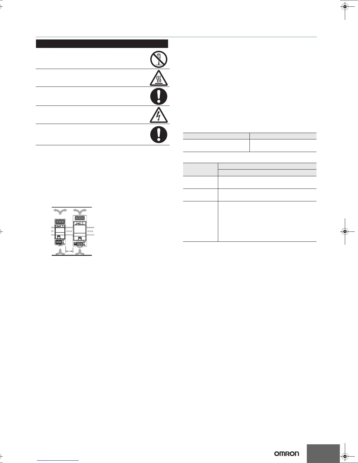
Mounting
Take adequate measures to ensure proper heat dissipation to
increase the long-term reliability of the Product. Be sure to allow
convection in the atmosphere around devices when mounting. Do
not use in locations where the ambient temperature exceeds the
range of the derating curve.
When cutting out holes for mounting, make sure that cuttings do not
enter the interior of the Products.
(15 W and 30 W Models)
Improper mounting will interfere with heat dissipation and may
occasionally result in deterioration or damage of internal parts. Use
the Product within the derating curve for the mounting direction that
is used.
Use a mounting bracket when the Product is mounted facing
horizontally.
Heat dissipation will be adversely affected. When the Product is
mounted facing horizontally, always place the side with the label
facing upward.
Always provide a space of 20 mm even when mounting horizontal or
facing horizontal. If a space of 20 mm is not available, reduce the
temperatures given in the derating curve on page 7 by 5°C and
provide a space of at least 10 mm.
(60 W, 120 W, 240 W, and 480 W Models)
Improper mounting will interfere with heat dissipation and may
occasionally result in deterioration or damage of internal parts. Use
the standard mounting method only.
The internal parts may occasionally deteriorate and be broken due to
adverse heat radiation. Do not loosen the screw on the side face of
the main body.
Wiring
Connect the ground completely. A protective earthing terminal
stipulated in safety standards is used. Electric shock or malfunction
may occur if the ground is not connected completely.
Minor fire may possibly occur. Ensure that input and output terminals
are wired correctly.
Do not apply more than 100 N force to the terminal block when
tightening it.
Be sure to remove the sheet covering the Product for machining
before power-ON so that it does not interfere with heat dissipation.
Use the following material for the wires to be connected to the S8VS
to prevent smoking or ignition caused by abnormal loads.
Recommended Wire Type
15 W and 30 W Models
60 W, 120 W, 240 W, and 480 W Models
Note: The rated current for output terminals is 10 A per terminal. Be
sure to use multiple terminals simultaneously for current that
exceeds the terminal rating.
Installation Environment
Do not use the Power Supply in locations subject to shocks or
vibrations. In particular, install the Power Supply as far away as
possible from contactors or other devices that are a vibration source.
Install the Power Supply well away from any sources of strong,
high-frequency noise and surge.
Operating Life
The life of a Power Supply is determined by the life of the electrolytic
capacitors used inside. Here, Arrhenius Law applies, i.e., the life will
be cut in half for each rise of 10°C or the life will be doubled for each
drop of 10°C. The life of the Power Supply can thus be increased by
reducing its internal temperature.
Ambient Operating and Storage Environments
Store the Power Supply at a temperature of −25 to 65°C and a
humidity of −25% to 90%.
Do not use the Power Supply in areas outside the derating curve
otherwise, internal parts may occasionally deteriorate or be
damaged.
Use the Power Supply at a humidity of 25% to 85%.
Do not use the Power Supply in locations subject to direct sunlight.
Do not use locations where liquids, foreign matter, or corrosive gases
may enter the interior of Products.
Minor electric shock, fire, or Product failure may
occasionally occur. Do not disassemble, modify, or repair
the Product or touch the interior of the Product.
Minor burns may occasionally occur. Do not touch the
Product while power is being supplied or immediately
after power is turned OFF.
Fire may occasionally occur. Tighten terminal screws to
the specified torque (15 and 30 W models: 0.8 to 1.0 N·m/
60, 120, 240, and 480 W models: 1.08 N·m).
Minor injury due to electric shock may occasionally occur.
Do not touch the terminals while power is being supplied.
Always close the terminal cover after wiring.
Minor electric shock, fire, or Product failure may
occasionally occur. Do not allow any pieces of metal or
conductors or any clippings or cuttings resulting from
installation work to enter the Product.
*1
*1
*2
*1. Convection of air
*2. 20 mm min.
Stranded wire Solid wire
AWG20 to 14
(0.5 to 2.0 mm
2
)
AWG20 to 16
(0.5 to 1.1 mm
2
)
Model
Recommended wire size
For screw terminal
S8VS-06024
AWG14 to 20
(Cross section 0.517 to 2.081 mm
2
)
S8VS-12024
S8VS-24024
AWG14 to 18
(Cross section 0.823 to 2.081 mm
2
)
S8VS-48024
Input terminals
AWG 14 to 16
(Cross section 1,309 to 2,081 mm
2
)
Output terminal
(see note 1.)
AWG 14
(Cross section 2,081 mm
2
)
T01E-EN-02+S8VS+Datasheet.fm Seite 11 Dienstag, 4. November 2008 6:58 18

 Loading...