S8VS
12
Overcurrent Protection
Internal parts may possibly deteriorate or be damaged if a
short-circuited or overcurrent state continues during operation.
Internal parts may possibly deteriorate or be damaged if the Power
Supply is used for applications with frequent inrush current or
overloading at the load end. Do not use the Power Supply for such
applications.
Dielectric Strength Test
If a high voltage is applied between an input and the case (FG), it will
pass though the LC of the built-in noise filter and energy will be
stored. If the high voltages used for dielectric strength testing are
turned ON and OFF with a switch, timer, or similar device, impulse
voltage will be generated when the voltage is turned OFF and
internal parts may possibly be damaged. To prevent the generation
of impulse voltages, reduce the applied voltage slowly with a variable
resistor on the test device or turn the voltage ON and OFF at the
zero-cross point.
Inrush Current
When two or more Power Supplies are connected to the same input,
the total current is the sum of the currents for each Supply. Select
fuses and circuit breakers giving sufficient consideration to the fusing
or operating characteristics so that fuses will not burn and breakers
will not break due to inrush current.
Output Voltage Adjuster (V.ADJ)
The output voltage adjuster (V.ADJ) may possibly be damaged if it is
turned with unnecessary force. Do not turn the adjuster with
excessive force.
After completing output voltage adjustment, be sure that the output
capacity or output current does not exceed the rated output capacity
or rated output current.
15 W, 30 W Models
If the output voltage is set to a value less than −10%, the
undervoltage alarm function may operate.
60 W, 120 W, 240 W, and 480 W Models
If the output voltage is set to a value less than 20 V (the factory
setting), the undervoltage alarm function may operate.
DIN Rail Mounting
To mount the Block on a DIN Rail, hook portion (A) of the Block onto
the rail and press the Block in direction (B).
To dismount the Block, pull down portion (C) with a flat-blade
screwdriver and pull out the Block.
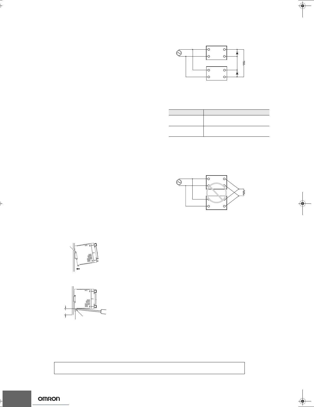
Series Operation
Two power supplies can be connected in series.
Note: 1. The diode is connected as shown in the figure. If the load is
short-circuited, a reverse voltage will be generated inside
the Power Supply. If this occurs the Power Supply may
possibly deteriorate or be damaged. Always connect a
diode as shown in the figure.
Select a diode having the following ratings.
2. Although Products having different specifications can be
connected in series, the current flowing through the load
must not exceed the smaller rated output current.
Parallel Operation
The Product is not designed for parallel operation.
In Case There Is No Output Voltage
The possible cause for no output voltage may be that the overcurrent
or overvoltage protection has operated. The internal protection may
operate if a large amount of surge voltage such as a lightening surge
occurs while turning ON the power supply.
In case there is no output voltage, please check the following points
before contacting us:
• Checking overload protected status:
Check whether the load is in overload status or is short-circuited.
Remove wires to load when checking.
• Checking overvoltage or internal protection (except for 15 W
models):
Turn the power supply OFF once, and leave it OFF for at least 3
minutes. Then turn it ON again to see if this clears the condition.
Buzzing Noise When the Input Is Turned ON
(120 W, 240 W, and 480 W Models)
A harmonic current suppression circuit is built into the Power Supply.
This circuit can create noise when the input is turned ON, but it will
last only until the internal circuits stabilize and does not indicate any
problem in the Product.
(B)
(A)
(C)
30 mm min.
Track stopper
Type Schottky Barrier diode
Dielectric strength
(V
RRM)
Twice the rated output voltage or
above
Forward current
(I
F)
Twice the rated output current or
above
+V
−V
+V
−V
Correct
AC (L)
AC (N)
AC (L)
AC (N)
+V
−V
+V
−V
Incorrect
AC (L)
AC (N)
AC (L)
AC (N)
In the interest of product improvement, specifications are subject to change without notice.
ALL DIMENSIONS SHOWN ARE IN MILLIMETERS.
To convert millimeters into inches, multiply by 0.03937. To convert grams into ounces, multiply by 0.03527.
Cat.No. T01E-EN-02_OEE
T01E-EN-02+S8VS+Datasheet.fm Seite 12 Dienstag, 4. November 2008 6:58 18