EasyManua.ls Logo

Omron S8VS

Omron S8VS
12 pages
To Next Page IconTo Next Page
Loading...
1
Switch Mode Power Supply
S8VS 15/30/60/120/240/480 W Models
Compact High capacity, Natural Cooling Power Supply Range from
0.65 A up to 20 A with Output Voltage of 24 VDC
Only 6 models to cover all applications
EMI Class B Compliant
Output indicator LED green
Mount to DIN Rail.
Complies with SEMI F47-0200 (200 VAC input).
RoHS-compliant.
Safety standards:
UL508/60950-1,
CSA C22.2 No. 107.1/60950-1 (60 W to 480 W),
EN50178 (= VDE0160),
EN60950-1 (= VDE0805 Teil 1)
Note: Refer to Safety Precautions on page 11
Model Number Structure
Model Number Legend
Ordering Information
List of Models
1 2
S8VS- @@@@@
1. Power Ratings
015: 15 W
030: 30 W
060: 60 W
120: 120 W
240: 240 W
480: 480 W
2. Output voltage
24: 24 V
Power ratings Input voltage Output voltage Output current Model number
15 W
100 to 240 VAC 24 VDC
0.65 A S8VS-01524
30 W 1.3 A S8VS-03024
60 W 2.5 A S8VS-06024
120 W 5 A S8VS-12024
240 W 10 A S8VS-24024
480 W
20 A
Peak current 30 A (200 VAC)
S8VS-48024
T01E-EN-02+S8VS+Datasheet.fm Seite 1 Dienstag, 4. November 2008 6:58 18

Other manuals for Omron S8VS

Question and Answer IconNeed help?

Do you have a question about the Omron S8VS and is the answer not in the manual?

Omron S8VS Specifications

General IconGeneral
BrandOmron
ModelS8VS
CategoryPower Supply
LanguageEnglish

Summary

Model Number Structure

Model Number Legend

Explains the components of the product's model number.

Ordering Information

List of Models

Lists the available power supply models with their ratings and part numbers.

Specifications

Approved Standards

Lists the safety and regulatory standards the product complies with.

SEMI Compliance

Details compliance with SEMI F47-0200 for power supply performance.

Connections

Block Diagrams

Illustrates the internal circuitry block diagrams for various models.

Construction and Nomenclature

Nomenclature

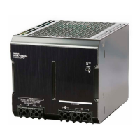
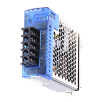
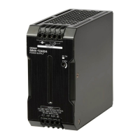
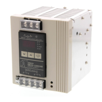
Identifies and explains the parts and terminals of the power supply units.

Engineering Data

Derating Curve

Shows how load capacity changes with ambient temperature for different mounting methods.

Mounting

Provides guidelines and illustrations for mounting the power supply units.

Overload Protection

Overload Protection Graphs

Displays output voltage behavior under overload conditions for different models.

Undervoltage Alarm Indication

Explains the function of the undervoltage indicator LED.

Reliability and Life Expectancy

Provides reference values for reliability (MTBF) and life expectancy.

Inrush Current, Startup, and Hold Time

Details the timing characteristics of the power supply during startup and operation.

Overvoltage Protection

Dimensions

Mounting Brackets

Safety Precautions

Wiring

Provides guidelines on connecting input and output wires to the power supply.

Recommended Wire Type

Specifies the recommended wire sizes for different models and terminals.

Precautions for Safe Use

Offers essential safety advice for handling and installing the power supply.

Mounting Precautions

Advises on proper mounting to ensure heat dissipation and prevent damage.

Installation Environment

Describes suitable environmental conditions for installing the power supply.

Operating Life

Discusses factors affecting the power supply's lifespan, especially temperature.

Ambient Operating and Storage Environments

Specifies temperature and humidity ranges for operation and storage.

Overcurrent Protection

Dielectric Strength Test

Explains procedures and precautions for dielectric strength testing.

Inrush Current Considerations

Discusses considerations for connecting multiple power supplies regarding inrush current.

Output Voltage Adjuster (V.ADJ)

Provides instructions and warnings for using the output voltage adjustment.

DIN Rail Mounting

Details the procedure for mounting the power supply units onto a DIN rail.

Series Operation

Parallel Operation

No Output Voltage Troubleshooting

Buzzing Noise When Input Is Turned ON

Related product manuals