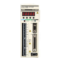
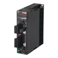
Do you have a question about the Omron SMARTSTEP 2 R7D-BP04H and is the answer not in the manual?
Details Omron's exclusive warranty for products, excluding other implied warranties.
Outlines Omron's limitations of liability and disclaims warranties for specific conditions.
Lists general safety precautions related to product installation and handling.
Provides detailed external dimensions and mounting hole information for components.
Lists general and control specifications for the SMARTSTEP 2 Servo Drives.
Details the general specifications and characteristics of OMNUC G-Series Servomotors.
Covers essential installation requirements for Servo Drives, Servomotors, and Decelerators.
Provides detailed descriptions of all user-configurable parameters.
Lists essential checks before turning on the power and initial setup steps.
Describes procedures for testing the system's electrical and mechanical operation.
Explains the purpose and methods for adjusting servo system gains.
Details the automatic gain adjustment using realtime estimation.
Describes the autotuning process for estimating load inertia and setting optimal gain.
Explains preliminary checks and cautions for handling problems.
Lists and explains all alarm codes and their meanings.
Provides methods for diagnosing and resolving issues based on symptoms and causes.
| Model | R7D-BP04H |
|---|---|
| Category | Servo Drives |
| Motor Capacity | 400 W |
| Output Power | 400 W |
| Control Method | PWM control |
| Series | SMARTSTEP 2 |
| Protection Functions | Overvoltage, Undervoltage, Overheat, Encoder Error |
| Communication Interface | RS-485 |
| Ambient Operating Temperature | 0 to 55°C |
| Storage Temperature | -20°C to 65°C |
| Vibration Resistance | 4.9 m/s² |
| Shock Resistance | 98 m/s² |
| Supply Voltage | 200 to 230 VAC |
| Ambient Operating Humidity | 20% to 85% (with no condensation) |


