EasyManua.ls Logo

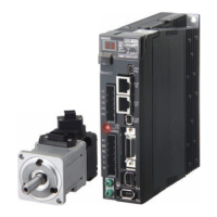
Omron R88M-K40030H-S2 User Manual

Omron R88M-K40030H-S2
484 pages
To Next Page IconTo Next Page
Page #1 background imageLoading...
Page #1 background image
Cat. No. I573-E1-03
USER’S MANUAL
OMNUC G5 SERIES
R88M-K@
(AC Servomotors)
R88D-KN@-ECT-R
(AC Servo Drives)
AC SERVOMOTORS/SERVO DRIVES
WITH BUILT-IN EtherCAT COMMUNICATIONS

Table of Contents

Questions and Answers:

Omron R88M-K40030H-S2 Specifications

General IconGeneral
TypeAC Servo Motor
ModelR88M-K40030H-S2
Rated Output Power400 W
Voltage200 VAC
Protection ClassIP65
Rated Torque1.27 Nm
Rated Speed3000 rpm
Maximum Speed5000 rpm

Summary

Specifications

3-1 Servo Drive Specifications

Details general specifications, international standards, and EC directives for Servo Drives.

3-2 Overload Characteristics (Electronic Thermal Function)

Explains the overload protection function and shows overload characteristics graphs.

3-3 Servomotor Specifications

Provides general specifications for OMNUC G5-Series AC Servomotors, including compliance standards.

System Design

4-1 Installation Conditions

Details space conditions, mounting direction, and environment operating conditions for Servo Drive installation.

4-2 Wiring

Provides peripheral equipment connection examples for single-phase and 3-phase input servo drives.

4-3 Wiring Conforming to EMC Directives

Details wiring requirements for EMC Directive conformance, including panel structure and cable shielding.

4-4 Regenerative Energy Absorption

Explains regenerative energy absorption and how to calculate it.

EtherCAT Communications

5-4 Process Data Objects (PDOs)

Explains PDOs for cyclic communications and PDO mapping settings for application objects.

Drive Profile

6-3 Cyclic Synchronous Position Mode

Explains position control using cyclic synchronization, including target position and speed/torque control.

6-5 Touch Probe Function (Latch Function)

Describes the latch function for capturing position actual value and lists related objects and trigger signal settings.

6-6 Fully-closed Control

Explains achieving accurate positioning using external encoders for fully-closed control systems.

Applied Functions

7-4 Backlash Compensation

Explains backlash compensation for position and fully-closed control and lists objects requiring settings.

7-5 Brake Interlock

Explains setting output timing for brake interlock (BKIR) and lists objects requiring settings.

7-6 Electronic Gear Function

Explains the electronic gear function for position control and fully-closed control modes. Lists objects requiring settings.

7-8 Gain Switching Function

Explains switching position loop and speed loop gain and lists objects requiring settings.

Safety Function

8-1 Safe Torque OFF Function

Details the STO function, its PFH value, and precautions for safe use.

8-2 Operation Example

Illustrates operation timings to a safety status, including servo ON/OFF and EDM output.

8-3 Connection Examples

Provides connection examples for using a safety controller with two safety inputs and one EDM output.

Details on Servo Parameter Objects

9-2 Gain Settings

Explains Position Loop Gain 1 and its purpose, and shows example graphs for gain changes.

9-3 Vibration Suppression Settings

Details Adaptive Filter Selection, Notch 1 Frequency, Width, and Depth Settings.

Operation

Adjustment Functions

Troubleshooting and Maintenance

Related product manuals