3-58
3-5 Servo Relay Units and Cable Specifications
3
Specifications
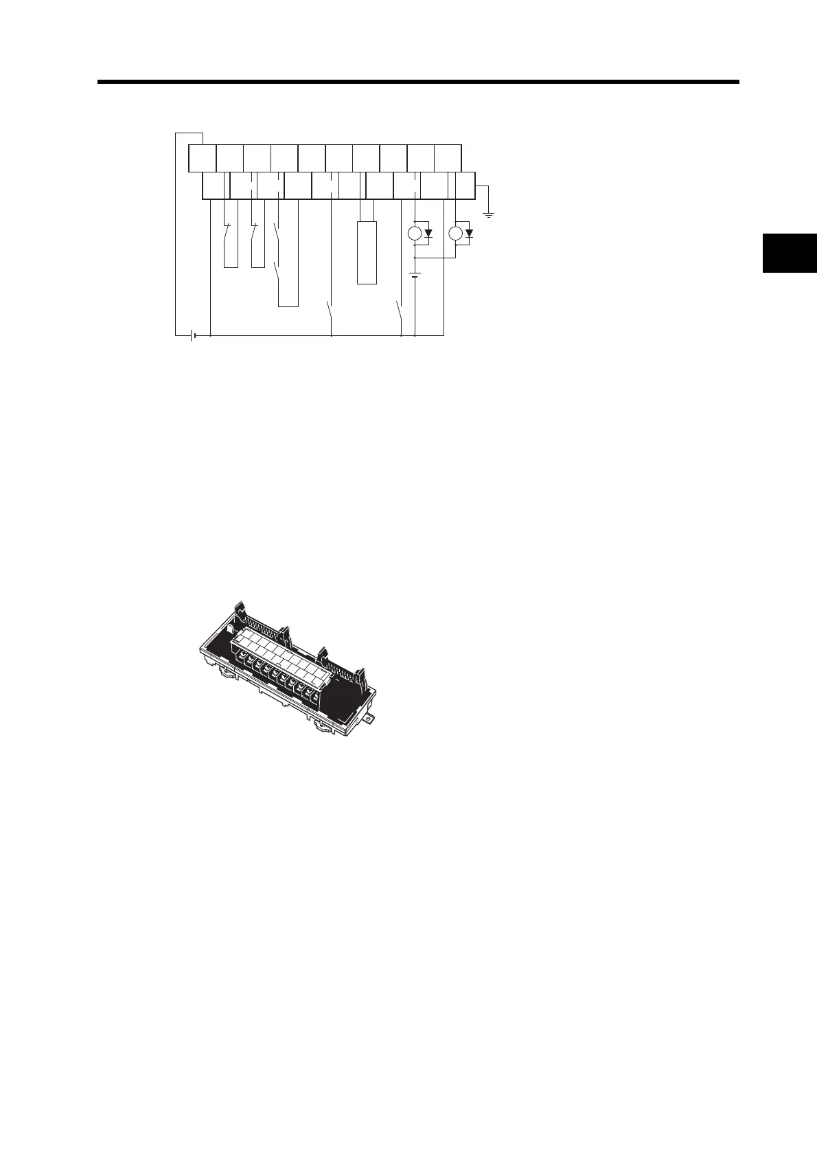
Wiring
*1. If this signal is input, the output pulse from the CQM1 will be input to the high-speed counter.
*2. Input this output signal to a CQM1 Input Unit.
*3. The XB contacts are used to turn ON/OFF the electromagnetic brake.
*4. The phase Z is an open collector.
*5. Do not connect unused terminals.
*6. The 0 V terminal is internally connected to the common terminals.
*7. Applicable crimp terminal: R1.25-3 (round with open end).
XW2B-20J6-8A
This Servo Relay Unit connects to the following OMRON Programmable Controllers.
CJ1M-CPU21/-CPU22/-CPU23 (for 1 axis)
0V
CW CCW RUN INP ALM BKIR
10
0
19
9
CW Z
RESET
ALMCOM
FG
24 VDC
X1 XB
24 VDC
X1
ECRST
CCW
+24 V
Common Common
CQM1 Input Unit
(*2)
(*3)
(*1) (*1)
0
1
2
3
4
5
6
7
8
9
10
11
12
13
14
15
16
17
18
19
 Loading...


