3-9
H Control Circuit Terminals
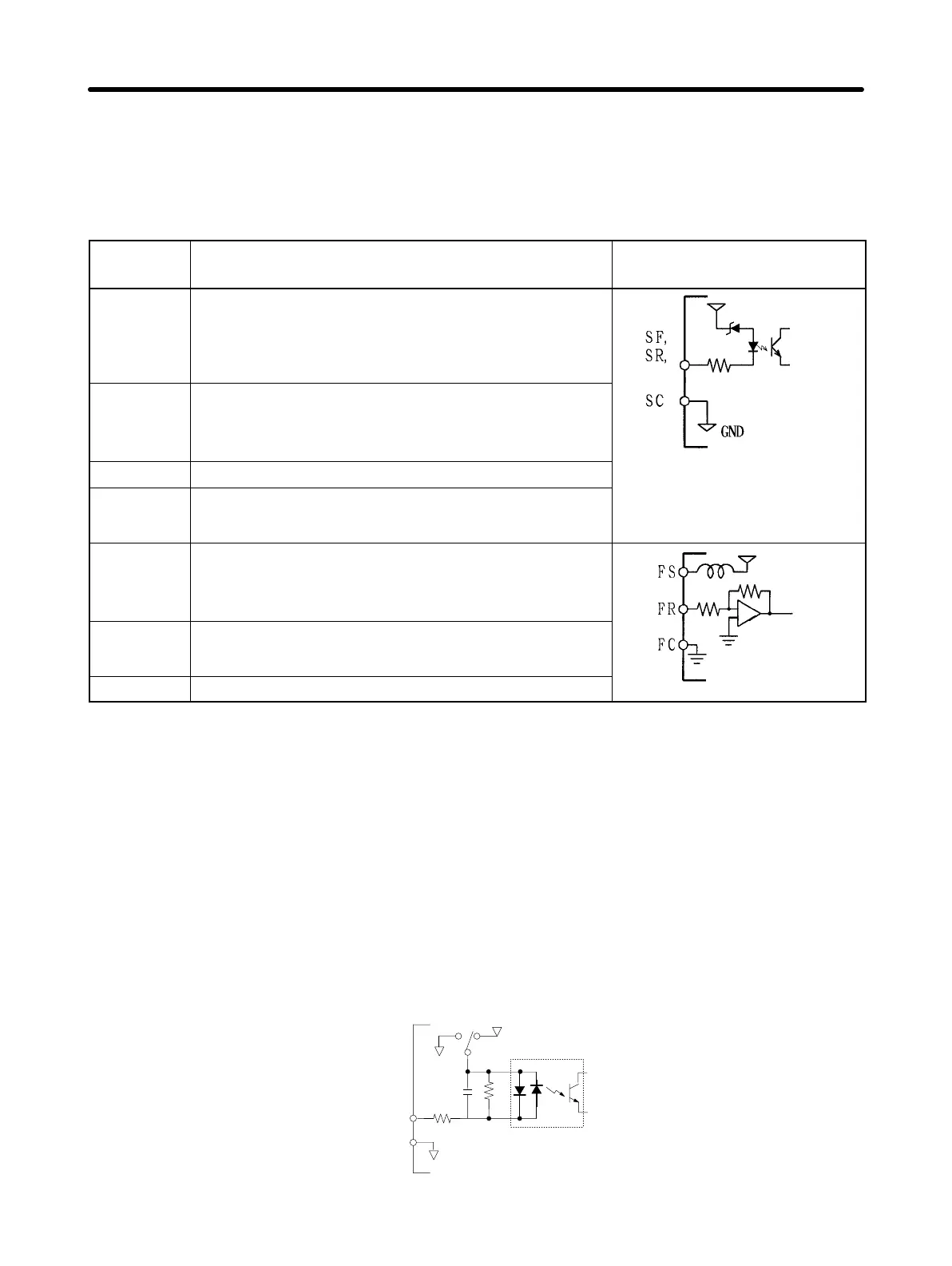
D Input Terminals (On Right-hand Side)
No external power supply is required because a built-in power supply is provided.
Terminal
symbol
Name and description Interface
SF Forward/Stop
When the terminal is ON, the motor rotates in
the forward direction. When the terminal is OFF,
the motor stops.
S1 to S3
24 V
6.2 V
SR Reverse/Stop
When the terminal is ON, the motor reverses.
When the terminal is OFF, the motor stops.
24 VDC at 8mA
S1 to S3
2.4 K
S1 to S3 Multi-function input (see note 1)
(See note 3)
SC Sequence input common
Input terminal common to SF, SR, and S1
FS Frequency reference power supply
Output voltage: 12 VDC
Permissible amperage: 20 mA
20 K
12 V
FR Frequency reference input (see note 2)
0 to 10 VDC is input.
Input impedance
FC Frequency reference common
20 kΩ
Note 1. Constant No. 06 (n06) is used to set this function. The following are the factory
settings of S1, S2, and S3.
S1: Fault reset (n06 = 1)
S2: External fault (input to contact a) (n07 = 2)
S3: Multi-step speed command 1 (n08 = 4)
Note 2. FR can be switched to an amperage input terminal (4 to 20 mA) by setting the
internal DIP switch and constant No. 02 (operation mode selection). For details,
refer to 7-2 Frequency Reference by Amperage Input.
Note 3. The circuit for a 400-VAC-class Inverter is as shown below.
GND
24 V
GND
3.3 K
SW2
SF
SR
S1 to S3
SC
360
0.1µ
Design Chapter 3