3-10
D Output Terminals (On Left-hand Side)
Terminal
symbol
Name and description Interface
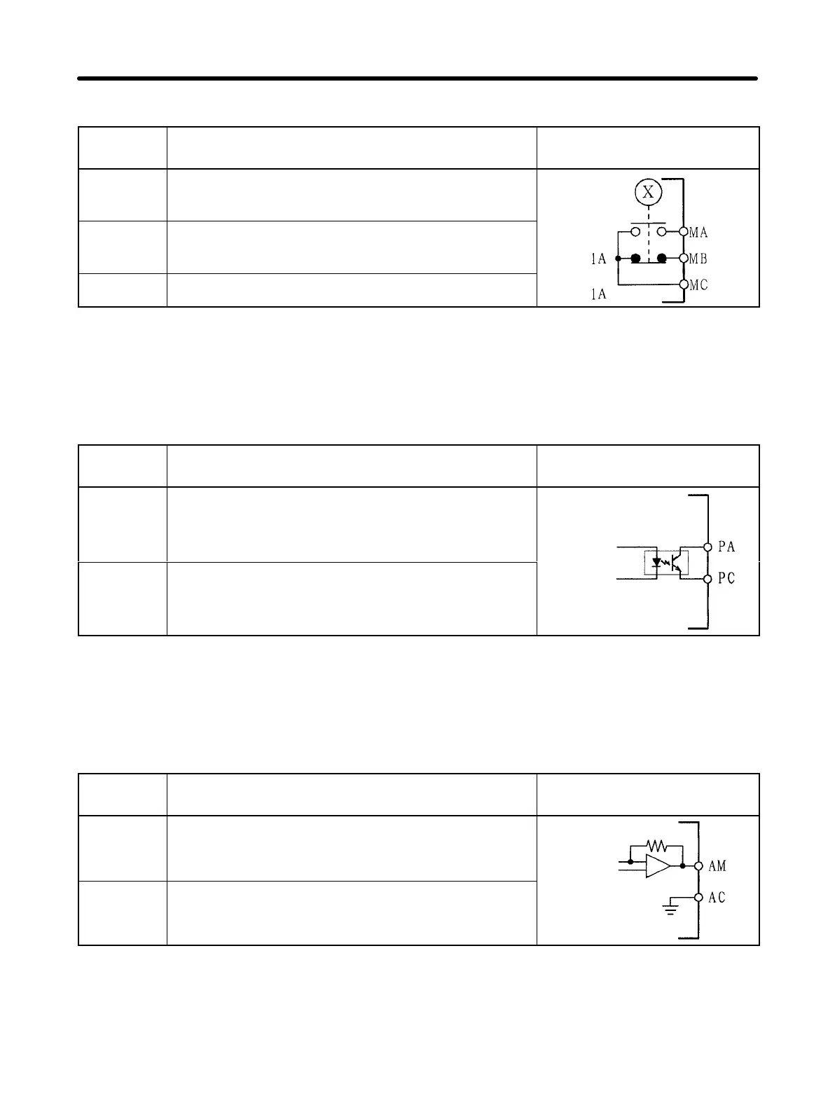
MA Multi-function contact output (contact a)
(see note)
MB Multi-function contact output (contact b)
(see note)
30 VDC
MC Multi-function contact output (common)
250 VAC
Note Constant No. 09 (n09) is used to set the function. This constant is factory set to
“operation in progress.”
D Output Terminals (On Right-hand Side)
Terminal
symbol
Name and description Interface
PA Multi-function photocoupler output (see
note)
PC Multi-function photocoupler output
(common)
50 mA at 48 VDC max.
Note Constant No. 10 (n10) is used to set this function. This constant is factory-set to
“fault reset.”
D Analog Output Terminals (On Right-hand Side)
Terminal
symbol
Name and description Interface
AM Multi-function analog output (see note)
AC Multi-function analog output (common)
2 mA at
0 to +10 VDC max.
Note Constant No. 44 (n44) is used to set this function and constant No. 45 (n45) is
used to set the multiplying factor, which are factory-set to “output frequency” and
“3V at maximum frequency” respectively.
Design Chapter 3