3-11
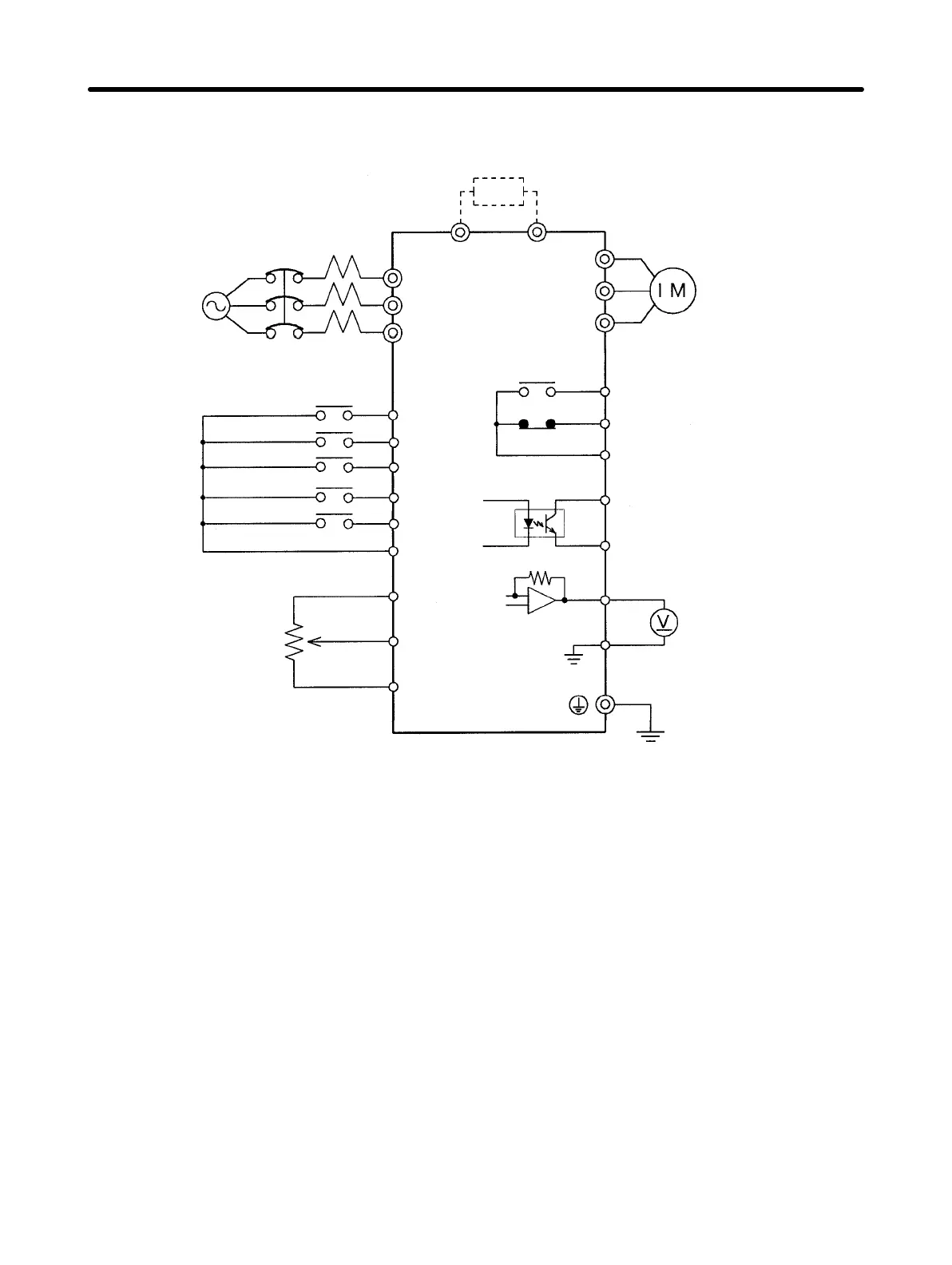
H Standard Connection Diagram
Power supply:
Three-phase, 200 to 230 VAC,
50/60 Hz
Three-phase, 380 to 460 VAC,
50/60 Hz
Molded-case circuit
breaker (MCCB)
Forward/Stop
Reverse/Stop
Multi-function input 2
Sequence input common
Frequency
reference
rheostat
(2 kΩ,
1/4 W min.)
Braking resistor (option)
Multi-function contact output
(Contact a)
(Contact b)
Common
B1 B2
R
S
T
U
V
W
SF
SR
S1
SC
FS (+12 V)
FR
FC
MA
MB
MC
PA
PC
AM
AC
Multi-function photocoupler
output
Multi-function photocoupler
output common
Multi-function analog output
Multi-function analog output
common
Voltmeter
S2
S3
Multi-function input 3
Multi-function input 1
Note 1. If a 3G3EV-ABjjjM is used in single-phase input mode, single-phase 200 to
240 VAC power with a frequency of 50/60 Hz must be input between terminals
R and S.
Note 2. For the 3-wire sequence, refer to the wiring on page 4-13.
Note 3. The input sequence power is built in.
Design Chapter 3