4-14
n02
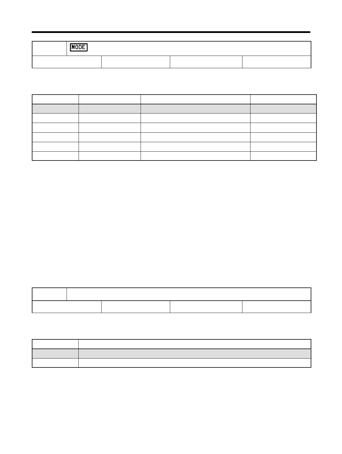
Operation Mode Selection
Setting range 0 to 5 Factory setting 0
This constant is used to specify whether the Inverter is to be operated with a Digital
Operator or external signals.
Value Run command Frequency reference DIP switch setting
0 Digital Operator Digital Operator (n11) OFF
1 Control terminal Digital Operator (n11) OFF
2 Digital Operator Control terminal (voltage input) OFF
3 Control terminal Control terminal (voltage input) OFF
4 Digital Operator Control terminal (amperage input) ON
5 Control terminal Control terminal (amperage input) ON
Note 1. The above setting operation can be performed when constant no. 02 is se-
lected. This operation is also possible when the dedicated indicator (“MODE”)
is lit.
Note 2. The DIP switch is located inside the Inverter. Use this switch to change the set-
ting when frequency references are to be input in terms of amperage (4 to 20
mA). For details, refer to Section 7-2 Frequency Reference by Amperage Input.
For voltage input, never set the DIP switch to ON. Doing so may damage the
equipment.
Note 3. If the frequency references (to be set to 2, 3, 4 or 5) are set through the control
terminals, analog command input will be treated as frequency reference 1. If
the multi-step speed command is used for multi-function input, frequency refer-
ences 2 to 8 will be available.
n03
Interruption Mode Selection
Setting range 0, 1 Factory setting 0
This constant is used to specify the interruption mode when the STOP/RESET Key is
pressed or the operation command is OFF.
Value Description
0 Frequency deceleration stop
1 Free running
Preparing for Operation Chapter 4