4-18
S The following is the frequency variable range with the up or down command.
Lower-limit frequency: Minimum output frequency determined with constant set
in n29 or frequency reference lower limit determined with constant set in n42,
whichever is larger.
Upper-limit frequency: Maximum frequency determined with constant set in n24
x frequency reference upper limit determined with constant set in n41/100.
If a frequency lower than the lower-limit frequency is designated, the lower-limit
frequency will be output and if a frequency higher than the upper-limit frequency
is designated, the upper-limit frequency will be output.
S The acceleration or deceleration rate with the up or down command will conform
to the constants set in n21 to n24 for the acceleration or deceleration time.
S Adjust the output frequency with the up or down command. The Inverter accepts
the up or down command as frequency instruction 1 and the Inverter begins
changing its output frequency starting with the lower-limit frequency.
S If frequency command 2 to 8 or the inching command is input while the Inverter is
increasing or decreasing its output frequency, the Inverter will give priority to the
command.
Note 4. If constants of 4, 5, and 6 are set in n06 to n08 respectively, the Inverter will be in
8-step speed operation.
Selected Frequency Command =
1 + (multi-step speed command 1) + (multi-step speed command 2) x 2 + (multi-step
speed command 3) x 4
Any of the above multi-step speed commands will be set to 1 when the multi-step speed
command is ON and 0 when the multi-step speed command is OFF.
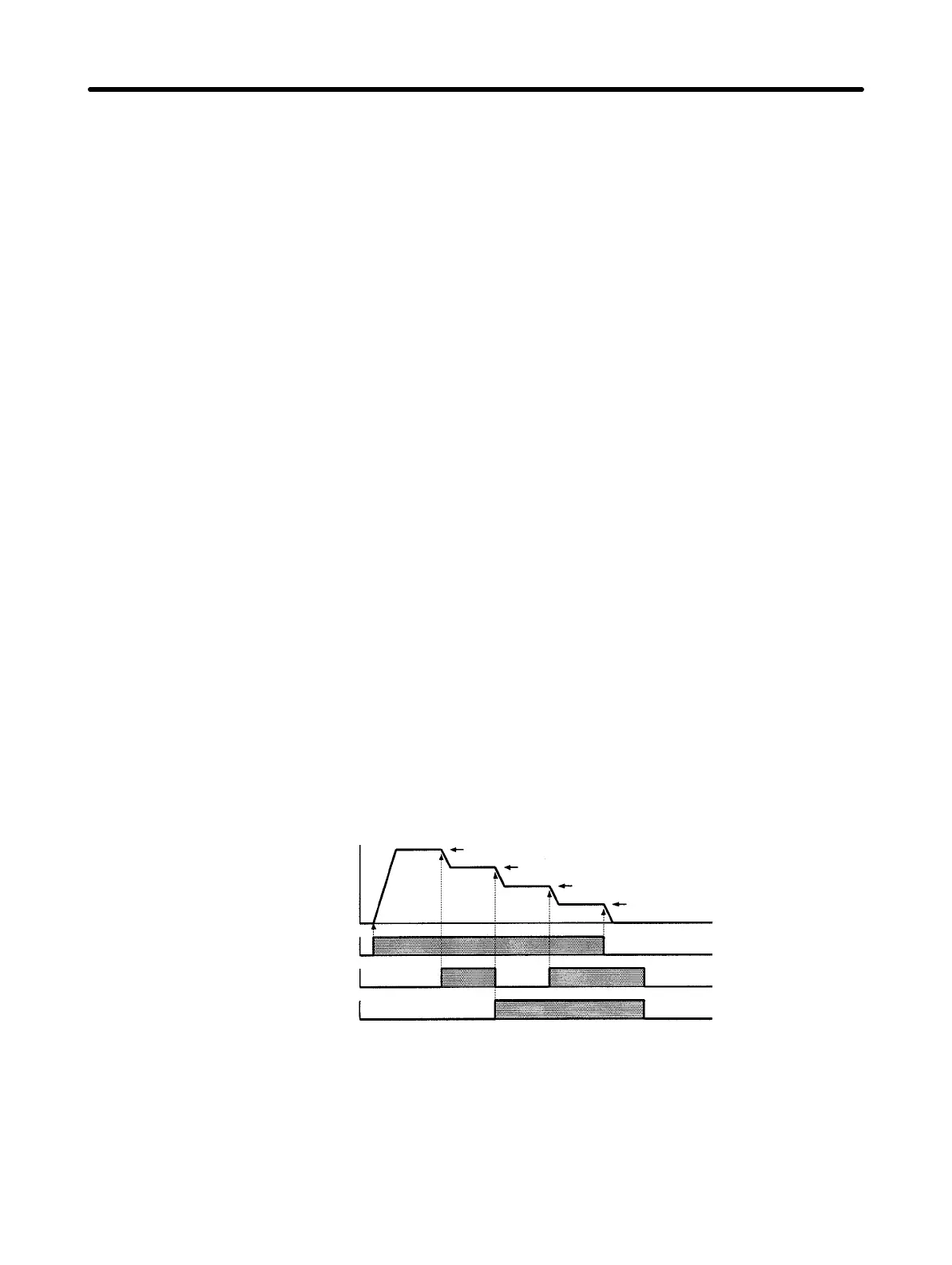
Multi-step Speed Operation Example
Output frequency
Operation command
Multi-step speed command 1
Multi-step speed command 2
Frequency command 1
Frequency command 2
Frequency command 3
Frequency command 4
Note Multi-step speed command 3 is also used as the acceleration/deceleration time
changeover command. When a frequency command (i.e., frequency command 5
to 8) turning ON multi-step speed command 3 is used, the Inverter will be in accel-
eration or deceleration operation with the constants set in n22 and n23 for accel-
eration and deceleration time 2.
Preparing for Operation Chapter 4