17-11
17 Analog Input/Output Option Board
CP2E CPU Unit Software User’s Manual(W614)
17-5 Analog Input Option Board
17
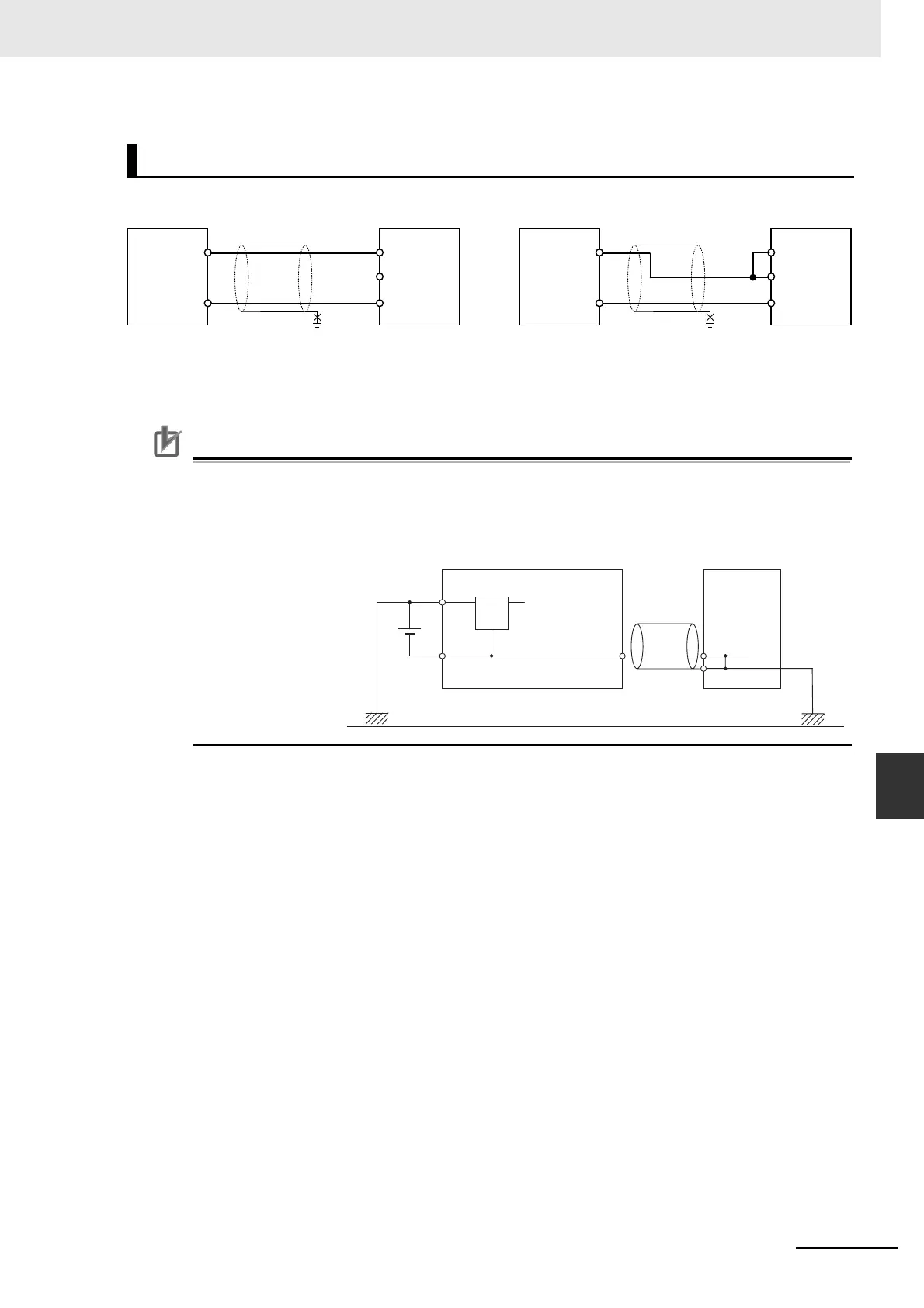
17-5-3 Wiring
To prevent noise, 2-core shielded twisted-pair cable should be used.
Note 1 When an input is not being used, short the V IN, I IN and COM terminals.
2 Separate wiring from power lines (AC power supply lines, high-voltage lines, etc.)
3 When there is noise in the power supply line, install a noise filter on the input section and the power supply.
Precautions for Correct UsePrecautions for Correct Use
When connecting the analog option board to an outside analog device, either ground the 0 V
side of the PLC’s external power supply or do not ground the PLC’s external power supply at all.
Otherwise the PLC’s external power supply may be shorted depending on the connection meth-
ods of the outside analog device. DO NOT ground the 24 V side of the PLC’s external power
supply, as shown in the following diagram.
Wiring for Analog Inputs
V IN
COM
I IN
V IN
COM
I IN
Analog
device with
voltage
output
Analog
Input
Option
Board
+
−
+
−
Analog
device with
current
output
Analog
Input
Option
Board
2-core shielded
twisted-pair cable
2-core shielded
twisted-pair cable
FG FG
24 V
0 V
0 V
Non-insulated DC power supply
0 V
Analog Device
FG
FG
Twisted-pair
cable
CPU Unit
+
Analog Option Board