A-85
Appendices
CP2E CPU Unit Software User’s Manual(W614)
A-2 Auxiliary Area Allocations by Address
App
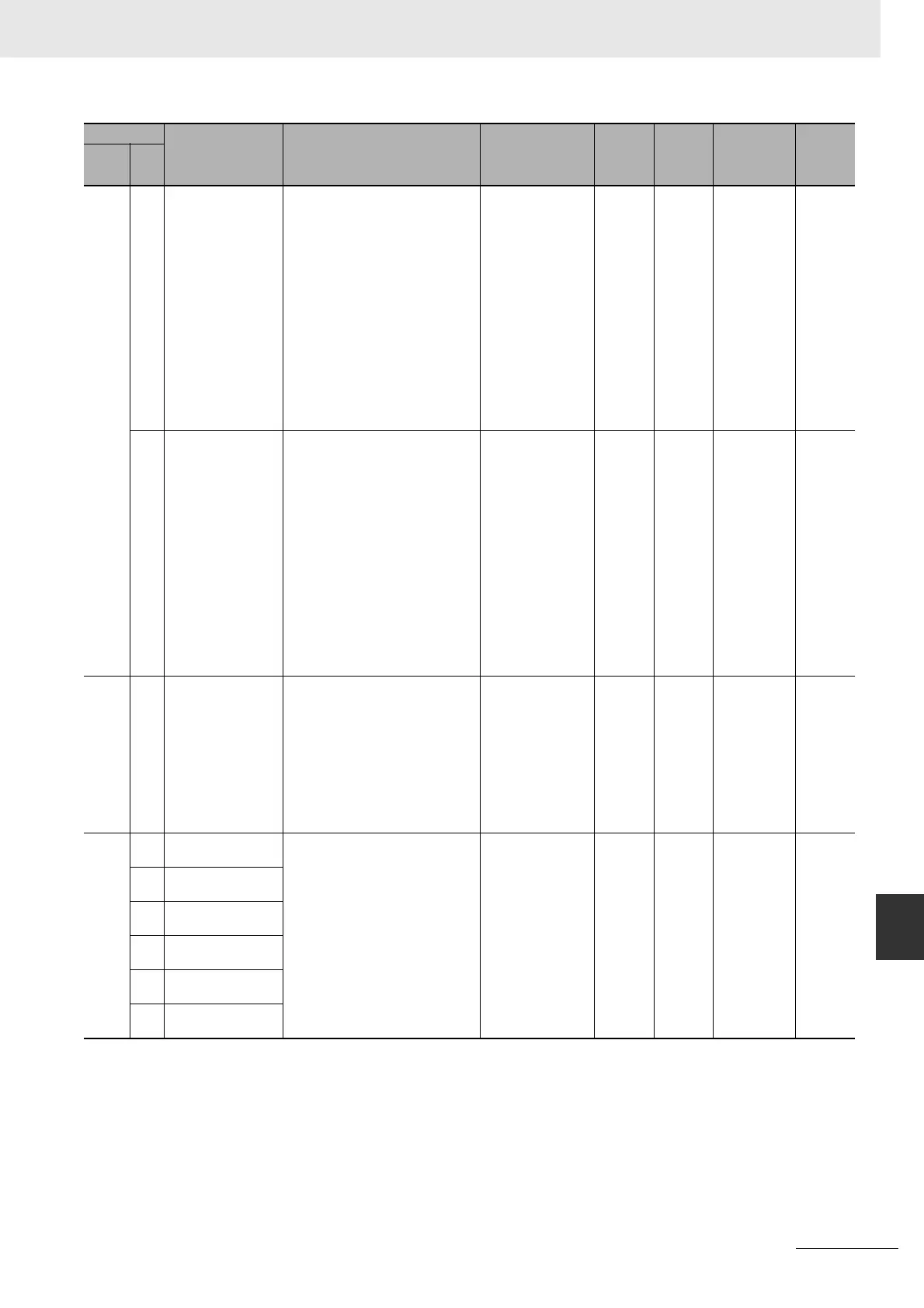
A528 00
to
07
Serial Port 1/
Built-in RS-232C Port
Error Flags
These flags indicate what kind of error
has occurred at the serial port 1 or
built-in RS-232C port.
• They are automatically turned OFF
when the serial port 1 or built-in
RS-232C port is restarted.
• Only bit 5 (timeout error) is valid in
NT Link mode.
• Serial PLC Link Polling Unit:
Bit 05: ON for timeout error.
Serial PLC Link Polled Unit:
Bit 02: ON for parity error.
Bit 03: ON for framing error.
Bit 04: ON for overrun error.
These bits can be cleared by the
CX-Programmer.
Bits 00 and 01: Not
used.
Bit 02: ON for parity
error.
Bit 03: ON for fram-
ing error.
Bit 04: ON for over-
run error.
Bit 05: ON for time-
out error.
Bits 06 and 07: Not
used.
Retained Cleared Refreshed
when commu-
nication error
occurs.
08
to
15
Serial Port 2/
Bult-in RS-485 Port
Error Flags (CP2E
N30/40/60 or
S-type CPU Unit
only)
These flags indicate what kind of error
has occurred at the serial port 2 or
built-in RS-485 port.
• They are automatically turned OFF
when the serial port 2 or built-in
RS-485 port is restarted.
• Only bit 5 (timeout error) is valid in
NT Link mode.
• Serial PLC Link Polling Unit:
Bit 13: ON for timeout error.
Serial PLC Link Polled Unit:
Bit 10: ON for parity error.
Bit 11: ON for framing error.
Bit 12: ON for overrun error.
These bits can be cleared by the
CX-Programmer.
Bits 08 and 09: Not
used.
Bit 10: ON for parity
error.
Bit 11: ON for fram-
ing error.
Bit 12: ON for over-
run error.
Bit 13: ON for time-
out error.
Bits 14 and 15: Not
used.
Retained Cleared Refreshed
when commu-
nication error
occurs.
A529 --- FAL/FALS Number for
System Error Simula-
tion
Set a dummy FAL/FALS number to
use to simulate the system error using
FAL or FALS.
Note When FAL or FALS is executed
and the number in A529 is the
same as the one specified in the
operand of the instruction, the
system error given in the oper-
and of the instruction will be gen-
erated instead of a user-defined
error.
0001 to 01FF hex:
FAL/FALS numbers
1 to 511
0000 or 0200 to
FFFF hex: No
FAL/FALS number
for system error sim-
ulation. (No error will
be generated.)
Retained Cleared ---
A531 00 High-speed Counter 0
Reset Bit
When the reset method is set to
Phase-Z signal + Software reset, the
corresponding high-speed counter's
PV will be reset if the phase-Z signal is
received while this bit is ON.
When the reset method is set to Soft-
ware reset, the corresponding
high-speed counter's PV will be reset
in the cycle when this bit turns ON.
OFF to ON: Reset Retained Cleared ---
01 High-speed Counter 1
Reset Bit
02 High-speed Counter 2
Reset Bit
03 High-speed Counter 3
Reset Bit
04 High-speed Counter 4
Reset Bit
05 High-speed Counter 5
Reset Bit
Address
Name Function Settings
Status
after
mode
change
Status at
startup
Write
timing
Related
flags,
settings
Words Bits