Specifications Appendix B
134
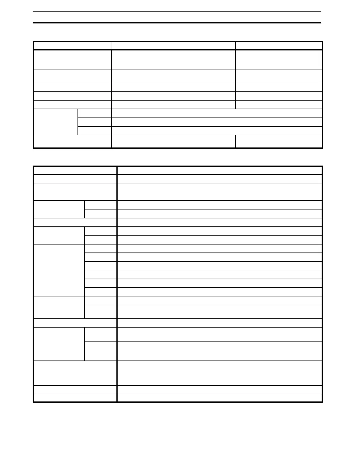
Output Specifications
Item Relays Transistors
Switching capacity Resistive loads: 2 A, 250 VAC
(cosf=1); 2 A, 24 VDC; 4 A/common
Inductive loads: 0.5 A, 250 VAC (cosf=0.4)
0.3 A, 24 VDC
+10%
/
–15%
ON/OFF delays ON: 10 µs max.
OFF: 10 µs max.
ON: 20 µs max.
OFF: 300 µs typical
Minimum permissible load 100 mA, 5 VDC ---
Leakage current --- 0.1 mA max.
Residual voltage --- 1.0 V max
No. of outputs SP10 4 pts. (2 circuits, 2 pts each)
SP16 6 pts. (3 circuits, 2 pts each)
SP20 8 pts. (4 circuits, 2 pts each)
Relay life Electrical: 100,000 operations min.
Mechanical: 20,000,000 operations min.
---
CPU Characteristics
Control method Stored program
I/O control Cyclic scan
Program Ladder diagram
Instruction length 1 step/instruction; 1 to 5 words/instruction
No. of instructions SP10 34: 12 basic, 5 arithmetic, 17 special
SP16, SP20 38: 12 basic, 5 arithmetic, 21 special
Processing speed 0.2 µs min./instruction; 0.72 µs min. average for reading/processing I/O status from memory
Program capacity SP10 144 words (approximately 100 instructions)
SP16, SP20 348 words (approximately 200 instructions)
I/O bits SP10 10 (bit 0000 to bit 0005 and bit 0100 to bit 0103)
SP16 16 (bit 0000 to bit 0009 and bit 0100 to bit 0105)
SP20 20 (bit 0000 to bit 0011 and bit 0100 to bit 0107)
Work bits SP10 36 (bit 0008 to bit 0015 and bit 0104 to bit 0215)
SP16 208 (bit 0010 to bit 0015, bit 0106 to bit 0215, and bit 1000 to bit 2015)
SP20 204 (bit 0012 to bit 0015, bit 0108 to bit 0215, and bit 1000 to bit 2015)
Dedicated bits SP10 20 (bit 0300 to bit 0315 and bit 0408 to bit 0411)
SP16, SP20 69 (bit 0300 to bit 0315, bit 0408 to bit 0411, bit 0515, bit 0700 to bit 0715, bit 0800 to bit 0815,
and bit 0900 to bit 0915)
Data-holding bits/link bits 256 data-holding bits of which 0, 64, or 128 can be designated as link bits
Timers/counters SP10 16 total: one 1-ms timer and one analog timer (0.1 to 25.0 s) plus 10-ms timers, 100-ms timers,
reversible drum counters, and decrementing counters
SP16, SP20 16 total: one 1-ms timer and two analog timers (0.01 to 2.50 s, 0.1 to 25.0 s, or 1 to 250 s) plus
10-ms timers, 100-ms timers, reversible drum counters, a high-speed counter, and
decrementing counters
Memory protection User program memory: RAM/EEPROM
Data-holding bits: RAM (20 days at 25°C*), can be stored in EEPROM
*The power supply must be turned on for at least 10 minutes to charge battery. Length of
memory backup is reduced at higher temperatures.
Program check Check for no END(01) instruction and for instruction errors when RUN mode is entered.
PC link Up to 4 CPUs linkable via Link Adapter (sold separately)