16
each PC, firstly to prevent voltage drops caused by surge currents and sec-
ondly, to prevent the breaker from malfunctioning.
The following diagrams show the proper way to connect the power source to
the PC. Refer to Appendix B Specifications for detailed specifications.
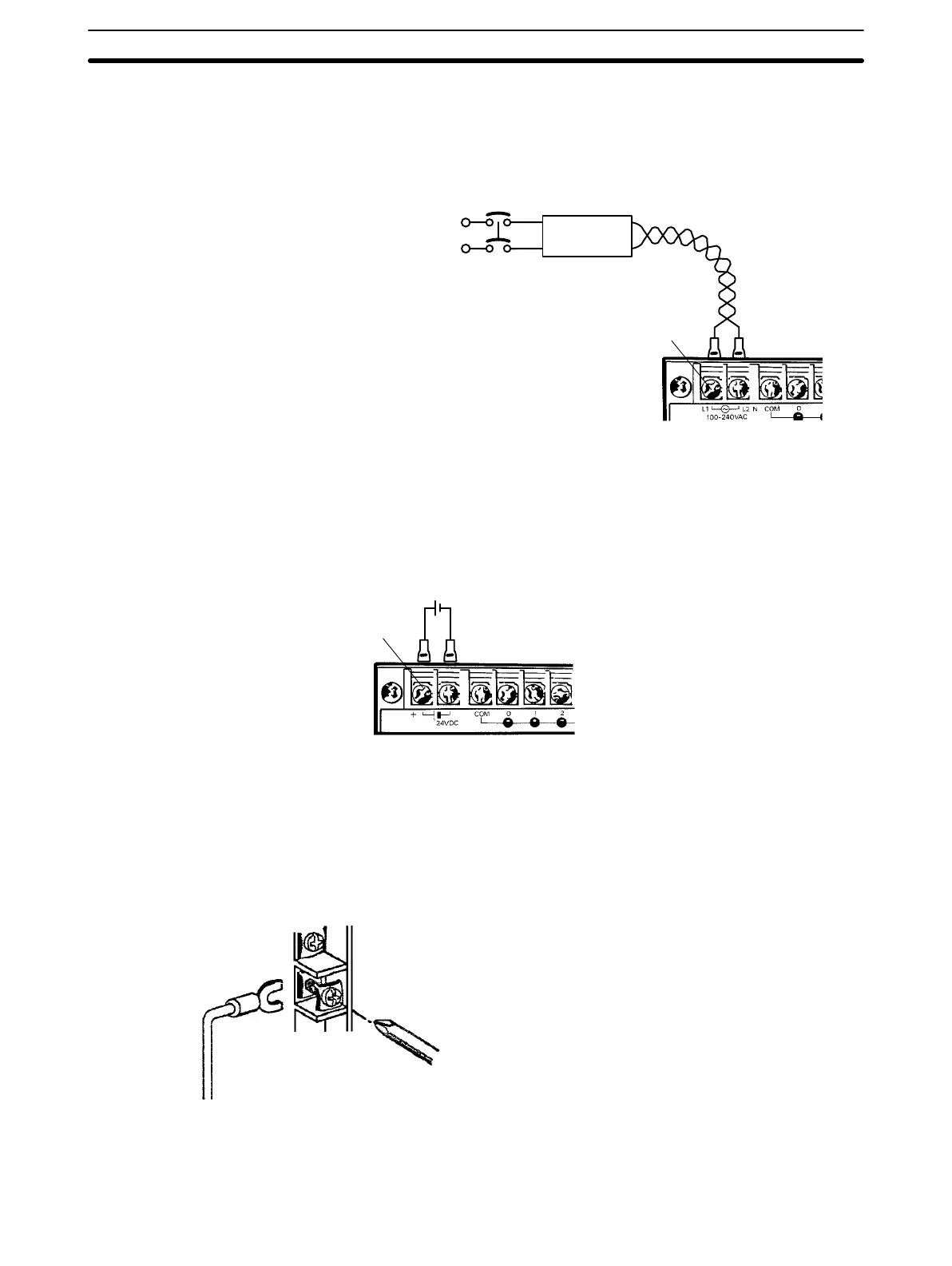
AC Connections
AC Power Source
• Supply 100 to 240
VAC, 50/60 Hz
Power Line
• Use twisted pair cable
(cross-sectional area of
2 mm
2
min.)
Breaker
1:1 Isolation
Transformer
M3.5 screws
To reduce noise interference from the power lines, use twisted pair cables.
Noise can also be significantly reduced by connecting a 1-to-1 isolation
transformer.
Note Do not short the positive and negative lines.
DC Connections Supply 24 VDC and keep voltage fluctuations within the specified range.
+
M3.5 screws
2-3-2 I/O Connections
Connect the I/O devices to the I/O terminals using wire with a cross-sectional
area of 1.04 to 2.63 mm
2
. The terminals have screws with M3.5 heads and
self-rising pressure plates. Connect the lead wires to the terminals as shown
below. Tighten the screws with a torque of 8 kg-cm maximum.
If you wish to attach solderless type terminals to the ends of the lead wires,
use terminals having the following dimensions.
Wiring Section 2-3