19
input devices such as sensors, etc., make sure that the power consumption
of the devices does not exceed the ratings of the PC.
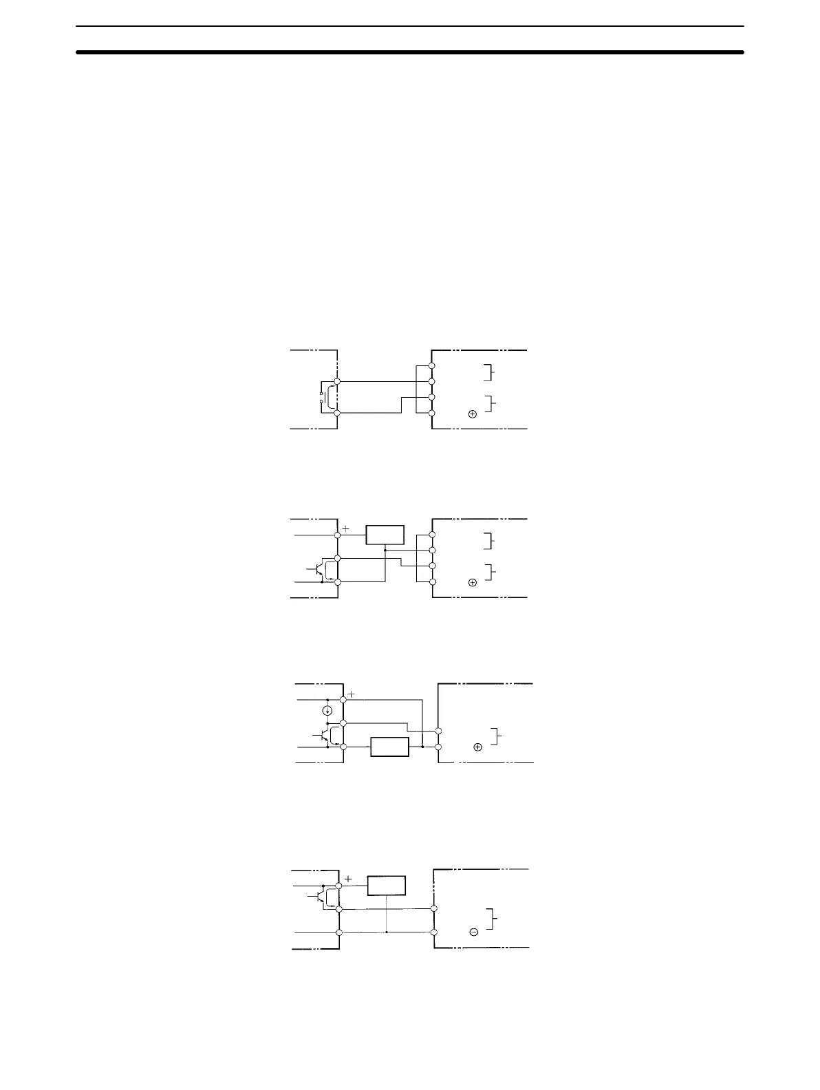
DC Input Examples The following diagrams show the correct way to wire the terminals on the
CPU. When wiring, work carefully to ensure that all terminals are wired cor-
rectly. If an input device is connected to an output point, damage may result.
Check all I/O devices to ensure they meet the specifications (refer to Appen-
dix B Specifications).
The DC inputs in the following diagrams are NPN (positive common). Re-
verse the polarity if PNP (negative common) is used.
Use the CPU’s 24 VDC power supply output to supply power to inputs. If the
maximum output current of 0.3 A is not sufficient, use a separate DC power
supply.
DC Input Devices
Power source for
external supply
DC input
7 mA
24 VDC
0 V
IN
COM
SP__
NPN Open-collector Outputs
Output
Sensor
power
supply
Power source for
external supply
DC input
24 VDC
0 V
IN
COM
SP__
7 mA
0 V
NPN Current Outputs
DC input
IN
COM
SP__
7 mA
0 V
Current
regulator
Output
Sensor
power
supply
Use the same power supply
for the input and sensor.
PNP Current Outputs
Output
Sensor
power
supply
DC input
IN
COM
SP__
7 mA
0 V
Note When using the DC model (SP__-D_-D), do not input the signal through a
NC contact (which makes the PC operate when the externally input signal
Wiring Section 2-3