73
bit operand is also placed on the same line as the mnemonic. All other oper-
ands are placed on lines after the instruction line, one operand per line and in
the same order as they appear in the ladder symbol for the instruction.
The address and instruction columns of the mnemonic code table are filled in
for the instruction word only. For all other lines, the left two columns are left
blank. If the instruction requires no definer or bit operand, the data column is
left blank for first line. It is a good idea to cross through any blank data col-
umn spaces (for all instruction words that do not require data) so that the
data column can be quickly scanned to see if any addresses have been left
out.
If an I/O bit, work bit, or dedicated bit address is used in the data column, the
left side of the column is left blank. If a DR, LR, or TC data address is used,
the data area abbreviation is placed on the left side and the address is place
on the right side. If a constant to be input, the number symbol (#) is placed
on the left side of the data column and the number to be input is placed on
the right side. Any numbers input as definers in the instruction word do not
require the number symbol on the right side. TC bits, once defined as a timer
or counter, take a TIM (timer) or CNT (counter) prefix.
When coding an instruction that has a function code, be sure to write in the
function code, which will be necessary when inputting the instruction via the
Programming Console.
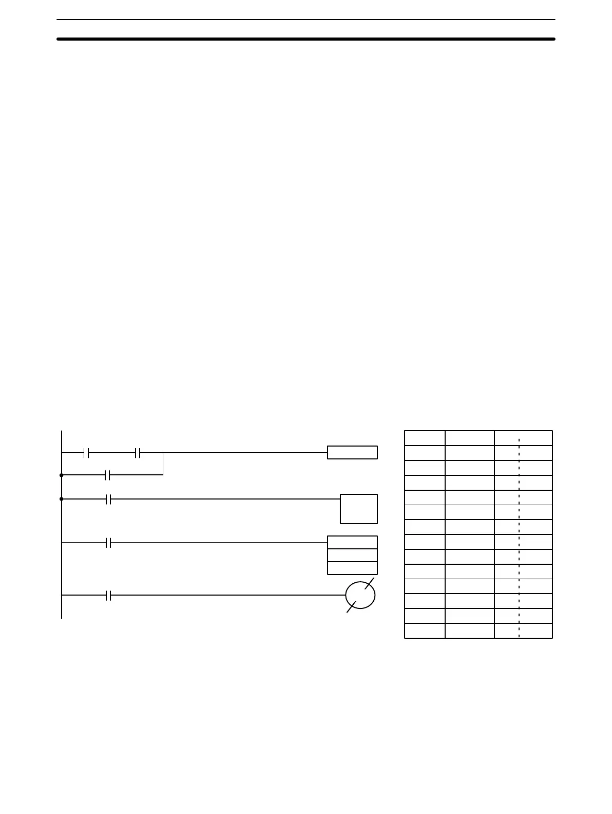
The following diagram and corresponding mnemonic code illustrates the
points described above.
Address Instruction Data
000 LD 0000
001 AND 0001
002 OR 0002
003 DIFU(10) 0215
004 LD 0005
005 TIM 00
# 0150
006 LD TIM 00
007 MOV(30) --
DR 00
LR 00
008 LD DR 0015
009 OUT NOT 0100
DIFU(10) 0215
0100
MOV(30)
DR 00
LR 00
TIM 00
0002
0005
DR 0015
0000 0001
TIM 00
#0150
If a right-hand instruction requires multiple instruction lines (such as
KEEP(12)), all of the lines for the instruction are entered before the
right-hand instruction. Each of the lines for the instruction is coded, starting
with LD or LD NOT, to form ‘logic blocks’ that are combined by the right-hand
instruction. An example of this for SFT(33) is shown below.
Multiple Instruction Lines
Instruction Set Section 3-7