Wiring Section 2-2
47
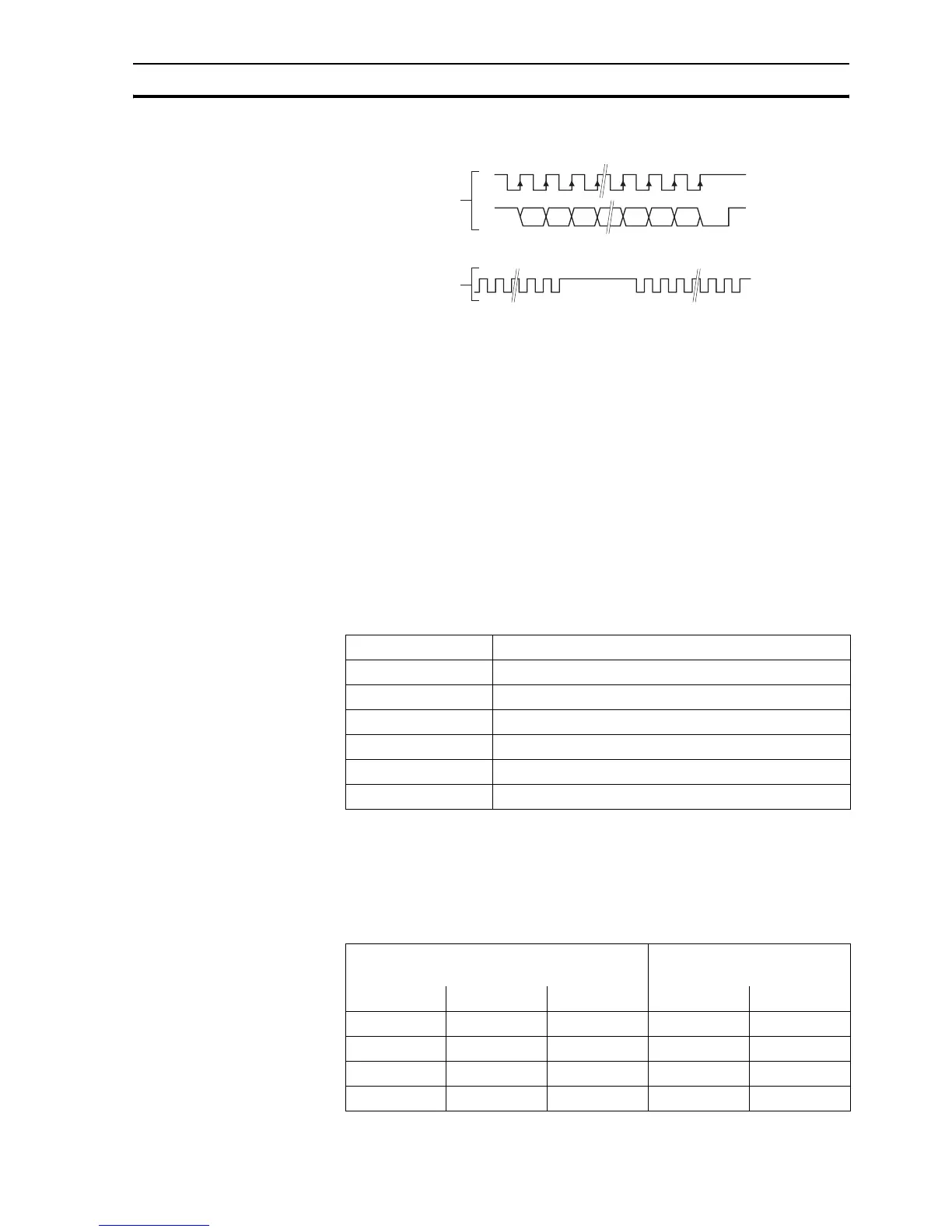
SSI pulses
The labels in the figure are:
A Timing diagram
B Clock sequence
CClock
DData
E MSB (Most Significant Bit)
F LSB (Least Significant Bit)
GClock frame
When the data is clocked into the CJ1W-MCH72, the position value is
interpreted. With this position value, it produces a value for MPOS and a
position error that is used to close the control loop.
The connections for SSI are:
/i
The table below and the figure give an example of how to connect the
Stegmann ATM 60-A encoder to the CJ1W-MCH72.
/i
Pin Signal
2Clock+
3Clock-
65 V
7Data+
8Data-
90 V
µs32
A
B
GG
C
D
EF
Note The CJ1W-MCH72 encoder interface does not have a termination inside. In case of
long distances or disturbed communication, add an external termination to the inter-
face.
Encoder CJ1W-MCH72 encoder inter-
face
Pin Signal Wire color Pin Signal
2 Data+ White 7 Data+
10 Data- Brown 8 Data-
3 Clock+ Yellow 2 Clock+
11 Clock- Lilac 3 Clock-
 Loading...


