Installation Section 2-3
50
2-3 Installation
2-3-1 Hardware installation
!Caution Obey the following precautions when you install the CJ1W-MCH72 in a PLC system:
• Turn off the power supply to the PLC before the installation or connection of the
CJ1W-MCH72.
• Use separate conduits or ducts for the I/O lines. This prevents noise from high-
tension lines or power lines.
• Do not remove the label on top of the CJ1W-MCH72 during the installation and
wiring. The label makes sure that no foreign matter can enter the unit.
• Remove the label on top of the CJ1W-MCH72 after the installation and wiring of the
unit. This makes sure that the unit cannot become overheated.
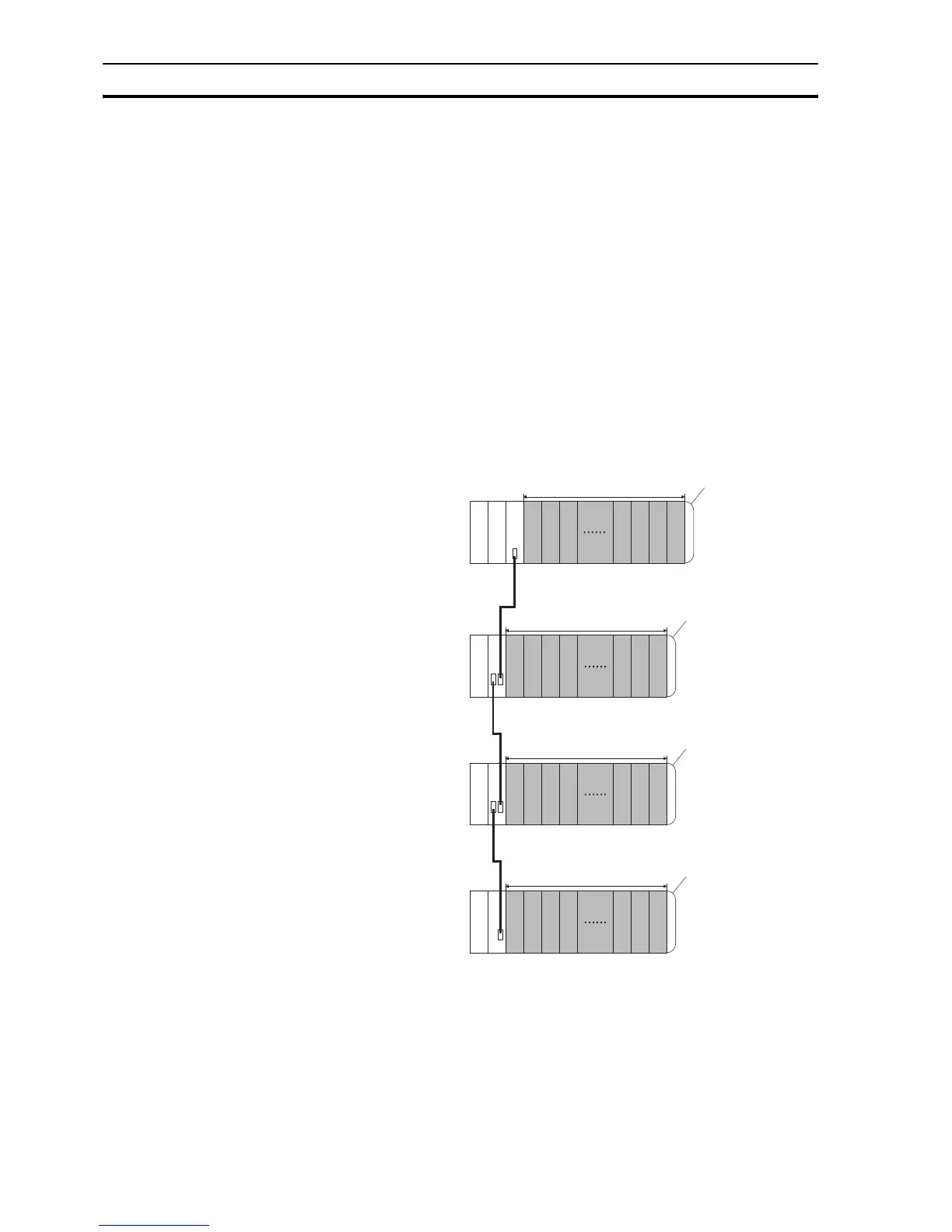
The CJ1W-MCH72 can be installed in any slot in a CJ-series CPU rack or in a
CJ-series expansion CPU rack. The CJ-series PLC supports up to 4
expansion CPU racks.
Up to 16 CPU bus units can be connected to one PLC. Also, the maximum
number of CJ1W-MCH72 units that can be connected to one PLC is 16.
Expansion racks
C
P
U
P
S
I
C
P
S
I
I
P
S
I
I
P
S
I
I
10 Units max.
10 Units max.
10 Units max.
10 Units max.
End cover
End cover
End cover
End cover
PS: Power Supply Unit
CPU: CPU Unit
IC: I/O Control Unit
II: I
/O Interface Unit
Expansion Backplane
Expansion Backplane
Expansion Backplane
PLC CPU rack
 Loading...


