6 Creating the Program ZEN Programmable Logic Module
OMRON ELECTRONICS, S.A. Page 18
6.3. Writing the Program
Two circuit lines, up to a total of 96 program lines, can be displayed on the
screen at the same time and a maximum of 3 contacts and one output per
program line can be entered.
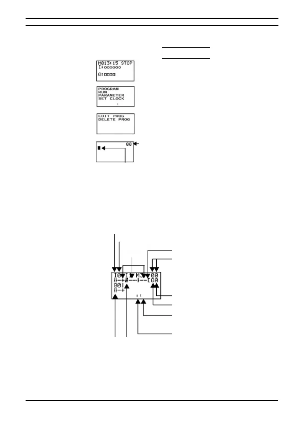
An example of a ladder diagram:
6.3.1. Writing Input Contacts
Once in the program editing screen, press “OK (1)” and the 0 (10) input
contact appears on the left-hand side of the first line of the program.
• STOP Mode
OK (1)
OK (1)
OK (1)
Shows the ladder program line number at
the cursor position.
Bit type
Address
Output Function
Program line number at cursor position
Connection
line
Bit type
Bit address
Indicates the presence of program lines
underneath the current line
Indicates the presence of program lines
above the current line
N.C. input
N.A. input

 Loading...


