IC
Load
Alarm output 1 & 2
(Terminal 3 & 4)
COMMON
(Terminal 5)
・Notice for Korea Radio Law
A급 기기(업무용 방송통신기자재)
이 기기는 업무용(A급) 전자파적합기기로서 판매자
또는 사용자는 이 점을 주의하시기 바라며,가정외의
지역에서 사용하는 것을 목적으로 합니다.
SuitabilityforUse
t
OmronCompaniesshallnotberesponsibleforconformitywithany
standards,codesorregulationswhichapplytothecombinationofthe
ProductintheBuyersapplicationoruseoftheProduct.AtBuyers
request,Omronwillprovideapplicablethirdpartycertificationdocuments
identifyingratingsandlimitationsofusewhichapplytotheProduct.This
informationbyitselfisnotsufficientforacompletedeterminationofthe
suitabilityoftheProductincombinationwiththeendproduct,machine,
system,orotherapplicationoruse.Buyershallbesolelyresponsiblefor
determiningappropriatenessoftheparticularProductwithrespectto
Buyersapplication,productorsystem.Buyershalltakeapplication
responsibilityinallcases.
NEVERUSETHEPRODUCTFORANAPPLICATIONINVOLVING
SERIOUSRISKTOLIFEORPROPERTYWITHOUTENSURINGTHAT
THESYSTEMASAWHOLEHASBEENDESIGNEDTOADDRESSTHE
RISKS,ANDTHATTHEOMRONPRODUCT(S)ISPROPERLYRATED
ANDINSTALLEDFORTHEINTENDEDUSEWITHINTHEOVERALL
EQUIPMENTORSYSTEM.
Jun,2019
D
OMRONCorporationIndustrialAutomationCompany
Contact:www.ia.omron.com
Kyoto,JAPAN
OMRONELECTRONICSLLC
2895GreenspointParkway,Suite200
HoffmanEstates,IL60169U.S.A.
Tel:(1)847-843-7900/Fax:(1)847-843-7787
OMRONASIAPACIFICPTE.LTD.
No.438AAlexandraRoad#05-05/08(Lobby2),
AlexandraTechnopark,
Singapore119967
Tel:(65)6835-3011/Fax:(65)6835-2711
OMRON(CHINA)CO.,LTD.
Room2211,BankofChinaTower,
200YinChengZhongRoad,
PuDongNewArea,Shanghai,200120,China
Tel:(86)21-5037-2222/Fax:(86)21-5037-2200
OMRONEUROPEB.V.
Wegalaan67-69,2132JDHoofddorp
TheNetherlands
Tel:(31)2356-81-300/Fax:(31)2356-81-388
RegionalHeadquarters
filter clogging detection
filter clogging detection
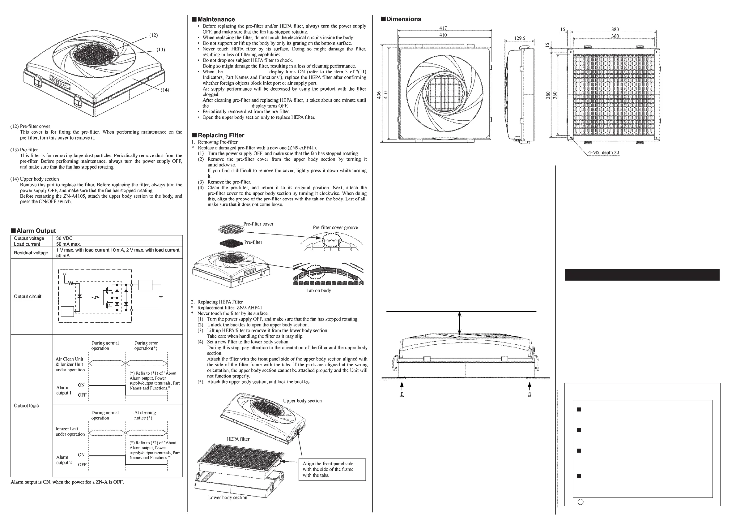
(unit:mm)
· When the Unit is mounted on a clean booth surface, rmly mount it using M5
screws. (tightening torque of 2.3 to 2.8 N·m)
· The upper body section can also be set at an angle of 90° to the lower body
section. Note, however, that when the upper body section si rotated 90°, HEPA
lter inside also must be rotated 90°. (See "Replacing the Filter.")
· When using the mounting screws (provided), use a mounting panel of thickness
14 mm or less, and thoroughly check the strength of the installation surface.
· The depth of the body mounting holes is 20 mm. When preparing your own
mounting screws, take the thickness of the installation surface into consideration
when selecting the screws.
· Allow at least 110 mm of space above the air inlet to ensure good intake of air.
· Do not support or lift up the body by only its grating on the bottom surface.
· Do not install the Unit with the air outlet facing up. Doing so may damage the
Unit.
· Use the sealing parts (provided) to prevent air from escaping between the body
and the installation surface.
· Since this product has a built-in fan, this product and equipment may resonate
and vibrate depending on the strength of the installation equipment and the clean
booth. When adopting, recommend that verify it with actual equipment. In such
cases, may be able to suppress the occurrence of vibration by reinforcing the
equipment installed to increase rigidity.
■
Installation
(Refer to the item 2, (7) DIP SW, Part Names and Functions)
· When the lter clogging detection display turns ON (refer to the item 3 of "(11)
Indicators, Part Names and Functions"), replace the HEPA lter after conrming
whether foreign objects block inlet port or air supply port.
Air supply performance will be decreased by using the product with the lter
clogged.
After cleaning pre-lter and replacing HEPA lter, it takes about one minute
until the lter clogging detection display turns OFF.
· The lter clogging detection display is set to turn ON when the air volume
becomes about 30% to 60% of the initial value. The threshold level of lter
clogging detection display will be changed by the inuence of ambient
temperature.
· By setting the terminal 2 of DIP switch (refer to "Part Names and Functions") to
ON, it is possible to cancel the lter clogging detection function.
■
Filter Clogging Detection Function
Min. 110 mm
Installation
surface
4-M5 screws
 Loading...


