Do you have a question about the Omron ZX2 Series and is the answer not in the manual?
Explains the meaning of signal words used throughout the manual for hazard indication.
Explains the alert symbols used in the manual for warnings and prohibitions.
Provides essential safety information regarding laser beam operation and handling.
Outlines general safety guidelines to ensure proper and safe operation of the product.
Details measures to prevent malfunctions and ensure optimal product performance.
Explains the structure and layout of the manual for effective navigation.
Clarifies the meaning of various symbols used to convey important information.
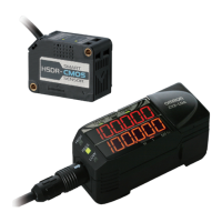
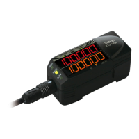
Identifies and describes the main components and their roles in the sensor system.
Provides step-by-step instructions for physically installing the sensor components.
Details the electrical connections and wire assignments for the sensor system.
Outlines the basic procedure for setting up a simple measurement.
Guides users through setting up specific measurement applications.
Shows how measured values and status are displayed in the operational mode.
Details the process for optimizing sensing conditions for a single workpiece.
Instructions for setting up and performing height measurements.
Procedures for measuring dimensional changes like steps and warpage.
Guides users on setting up the sensor for double sheet detection.
Details on configuring the sensor for thickness measurement.
Guidance on setting up measurements related to object positioning.
Procedures for measuring eccentricity and surface variations.
Optimizes sensing conditions based on response time and workpiece properties.
Improves measurement stability near judgment thresholds by adjusting hysteresis.
Configures the function to hold measured values at the end of a measurement period.
Allows storing and recalling up to four different sets of measurement settings.
Sets a reference value to "0" or a desired numeric value for deviation measurement.
Adjusts the display scale to show values different from actual measurements.
Configures the conversion of measurement results to analog current or voltage output.
Defines output behavior when errors occur or reset input is active.
Adjusts the timing for judgment outputs to match external devices.
Configures external signals for bank switching, timing, and reset operations.
Prevents signal interference when sensors are mounted closely together.
Disables all keys to prevent inadvertent changes to settings.
Resets all settings to their factory default values.
Lists common problems and their probable causes and countermeasures.
Details error codes displayed by the unit and their respective solutions.
Provides technical data, measurements, and operational ranges for the units.
Illustrates the timing sequences for I/O signals exchanged with external devices.
Presents typical performance characteristics like angle and linearity.
An alphabetical listing of topics and their corresponding page numbers for quick reference.
Records the manual's revision codes, dates, and changes made.
Visual flowcharts illustrating the transitions between different settings and modes.
| Model | ZX2 Series |
|---|---|
| Humidity | 35 to 85% RH (no condensation) |
| Output | Analog (voltage or current), Digital |
| Current Consumption | 100 mA max |
| Operating Temperature | 0 to 50°C |
| Vibration Resistance | 10 to 55 Hz, 1.5 mm double amplitude |