Installation Section 1-5
13
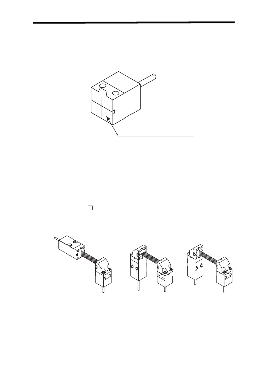
Optical Axis Adjustment
• Attach the optical axis adjustment seal provided with the Sensor Head to
the front of the Emitter. Adjust the laser beam radiated from the Emitter
so that it is aligned with the center of the cross on the seal. Always
remove the seal after completing the adjustment.
If you need more accurate adjustment of the optical axis, adjust it to maxi-
mize the value displayed on the Amplifier Unit.
Note: Do not touch the surface of the Emitter and Receiver on the Sensor
Head. Fingerprints or other contamination on the surface will interfere
with correct Sensor operation. If the surface is touched by mistake, clean
it by wiping it gently with a soft clean cloth.
Mounting the Side-view Attachment
• The ZX-XF 2 Side-view Attachment (order separately) can be
mounted to the Emitter, to the Receiver, or to both.
• To mount the Side-view Attachment, use the M2 screws provided and
tighten them to a torque of 0.08 N⋅m or less.
Emitter
Optical axis adjustment seal
Z157-E1-01C.book Page 13 Thursday, August 31, 2006 5:13 PM

 Loading...


