seat. Deeply pitted
or
cut valves must be replaced,
because grinding removes the margin.
Grind valve seats with a 45-degree stone. The
width
of
the
seat band should be 1/32 inch
to
3/64
inch
(0.
79
to
1.2 mm) wide. Grind only enough to
be sure
of
proper valve seating.
Place each valve
in its proper location. Check each
valve for a tight seat. Make several marks at regu-
lar intervals across the valve face using machinist's
bluing. Observe
if
the marks rub off uniformly when
the valve is rotated part
of
a turn against the seat.
The valve seat should contact the valve face evenly
at all points. The line of contact should be
at
the
center
of
the valve face.
Valve
Guides
Worn valve stem guides can
be
replaced from in-
side the valve chamber.
The
smaller diameter
of
the tapered valve guides must face toward the
valve head.
Tappets
are also replaceable from the valve cham-
ber, after the valve assemblies are removed first.
Valve
Guide
Removal
Procedure
1 . Before removing the valve guides, use
an
elec-
tric drill with a wire brush
to
remove carbon and
other foreign material from the top surface
of
the guides. Failure to
do
this may result in
damage
to
the guide bores.
2.
Drive the guides out with a
hammer
and a
valve
guide driver. Wear goggles while per-
forming this procedure.
lA CAUTION I Driving
out
the
old
valve guides can
damage the tappet bores.
Be
careful
not
to
strike the bores with the driver.
Valve
Guide
Installation
Procedure
1. Run a small polishing rod with crocus cloth
through the vaive guide holes, to clean out car-
bon and
other foreign materials.
2. Coat the outer edge
of
each new guide with
oit
it in
rests against the cylinder
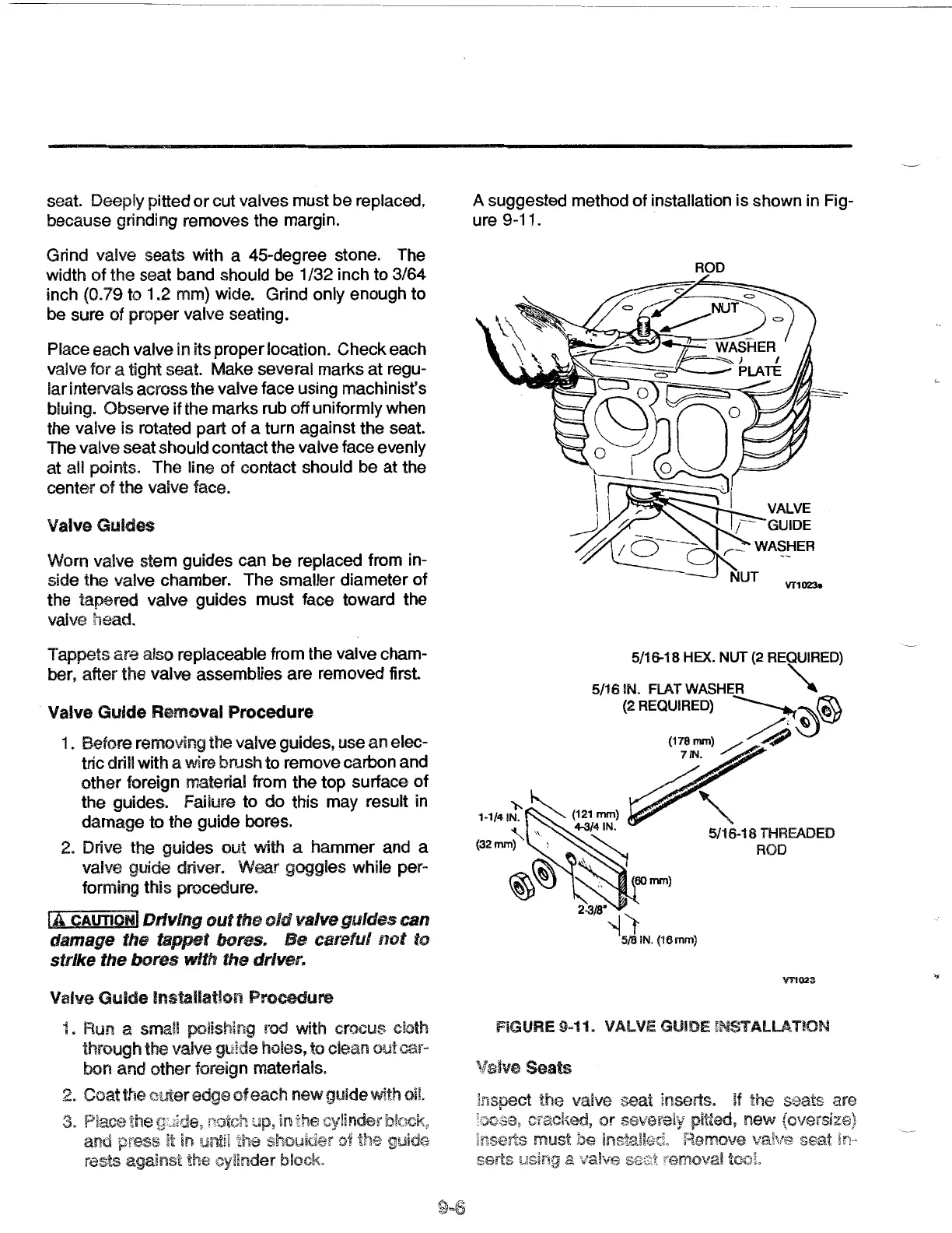
A suggested method
of
installation
is
shown in Fig-
ure
9-11.
ROD
5/16-18 HEX. NUT (2 REQUIRED)
5/161N. FLATWASHER
"""
(2 REQUIRED}
~~®
(178mm)
/4
7iN.
2-3/8"~
f
5/8 iN. (16
mm)
5/16-18 THREADED
ROD
FIGURE
9~11.
VALVE GUIDE
~NSTALLATION
Valve
Seats
 Loading...