2. Loosen the throttle stop screw locknut and
back the screw out away from the tang on the
throttle lever, while gently rotating the throttle
lever counterclockwise as far as if will go.
3. While gently holding the throttle lever counter-
clockwise as far as it will go, turn the stop screw
in until it just touches the tang. Then turn the
screw an additional 118-1/4 turn (clockwise)
and set and seal the locknut.
If the throttle stop screw adjustment is okay, recon-
nect the governor rod as follows:
1.
Insert the rod in the spring such that the shorter
hook wire is on the throttle side.
2. Hook the rod and spring into the grommet in the
throttle lever. (The spring should pull on one
side and the rod push on the other side
of
the
grommet when fully assembled.)
3. Pull the governor rod towards the plastic clip on
the end of the actuator lever as far as the
throttle stop screw permits. Leave the actuator
lever in its fully counterclockwise (rest) posi-
tion. Snap the dogleg on the end
of
the rod into
the slot in the clip that most closely lines up with
it. Use both hands so as not to bend the actua-
tor lever.
4.
Hook the spring into the slot in the end of the
actuator lever. When assembled, the spring
hook wires should not wrap around the gover-
nor rod.
5.
Move the actuator back and forth through its full
movement
to
make certain there is no sticking
or binding.
6. After installing the top panel, hook the spark
plug cable with the clip inside the panel to keep
it from interfering with the governor rod.
Idle Fuel Mixture
Adjustment:
These instructions
do
not apply
to
Spec F and later gensets.
1.
If the carburetor has been overhauled, gently
turn the idle and main fuel mixture screws in
by
hand until they seat.
For
Gasoline Gensets: Turn the idle mixture
screw out 1 turn and the main fuel mixture
screw out 1-3/8 turns so that the engine will
start and run.
6-15
For
LPG Gensets: Turn the idle mixture screw
out 1-1/4 turns and the main fuel mixture screw
out 2-1/2 turns
so
that the engine will start and
run.
lA CAUTION!
Forcing
a
mixture
adjusting
screw
in
tight
will
score
the needle
and
seat.
Turn
it
lightly
by
hand
only.
2. Start the genset and let it warm up for ten min-
utes under 1/2 to 3/4 rated load. (On vapor
withdrawal type LPG gensets it might be nec-
essary first to adjust the demand regulator and
supply pressure to get the genset to start. See
LPG
System-Vapor
Withdrawal.)
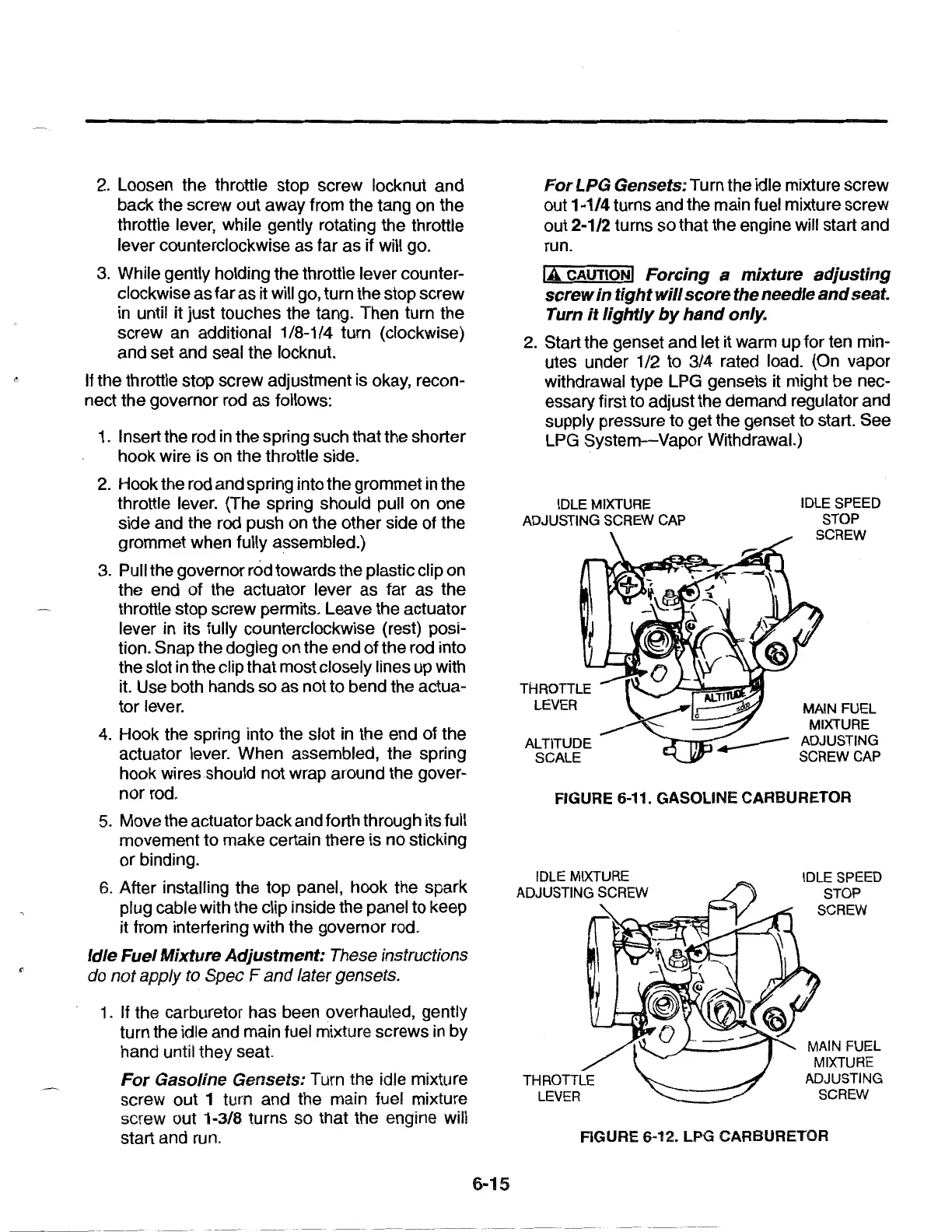
IDLE MIXTURE
ADJUSTING SCREW CAP
ALTITUDE
SCALE
IDLE SPEED
STOP
SCREW
MAIN FUEL
MIXTURE
~ADJUSTING
SCREW CAP
FIGURE 6-11. GASOLINE CARBURETOR
IDLE SPEED
STOP
SCREW
MAIN FUEL
MIXTURE
ADJUSTING
SCREW
FIGURE
6-12.LPG
CARBURETOR
 Loading...