3.
Disconnect the load (check for zero amps).
Turn the idle mixture adjusting screw clockwise
until the engine begins to stumble. Then,
counting the number of turns, turn the screw
counterclockwise until it begins to stumble
again. Set the screw halfway
in
between. For
closer adjustments, use a CO meter to adjust
to 6-8% CO (gasoline) or 4-6% CO (LPG). See
Troubleshooting
if
the engine runs roughly.
4.
Push the adjustment limiter cap on over the
mixture screw head such that it will allow equal
adjustment
in
either direction (gasoline carbu-
retors).
Main Fuel Mixture
Adjustment:
These instruc-
tions
do
not apply
to
Spec F and later gensets.
1.
Connect rated load.
A.
Load (watts) is the product of volts
(V)
and
amps (A).
Load (watts)
= V x A
(A 1.0 power factor, obtainable with a re-
sistance load bank, is assumed. True
rated output might not be obtained
if
appli-
ances are used as part of the load.)
B.
See Section
8.
Generator if output voltage
cannot be adjusted to within 1 0 percent of
rated voltage (Table
6-1
).
2.
Turn the main fuel mixture adjusting screw
clockwise until the engine begins to stumble.
Then, counting the number of turns, turn the
"\
"\%
screw counterclockwise until it begins to
stumble again. Set the screw halfway
in
be-
tween. For closer adjustments, use a CO meter
to adjust to 6-8% CO (gasoline) or 2-4% CO
(LPG). See
Troubleshooting if the engine runs
roughly.
3.
Push the adjustment limiter cap on over the
mixture screw head such that the cap pointer
indicates the current altitude (gasoline carbu-
retors).
TABLE
6-1. VOLTAGE SPECIFICATION
RATED MAXIMUM MINIMUM
OUTPUT NO-LOAD FULL-LOAD
VOLTAGE VOLTAGE VOLTAGE
120V, 1PH
126
114
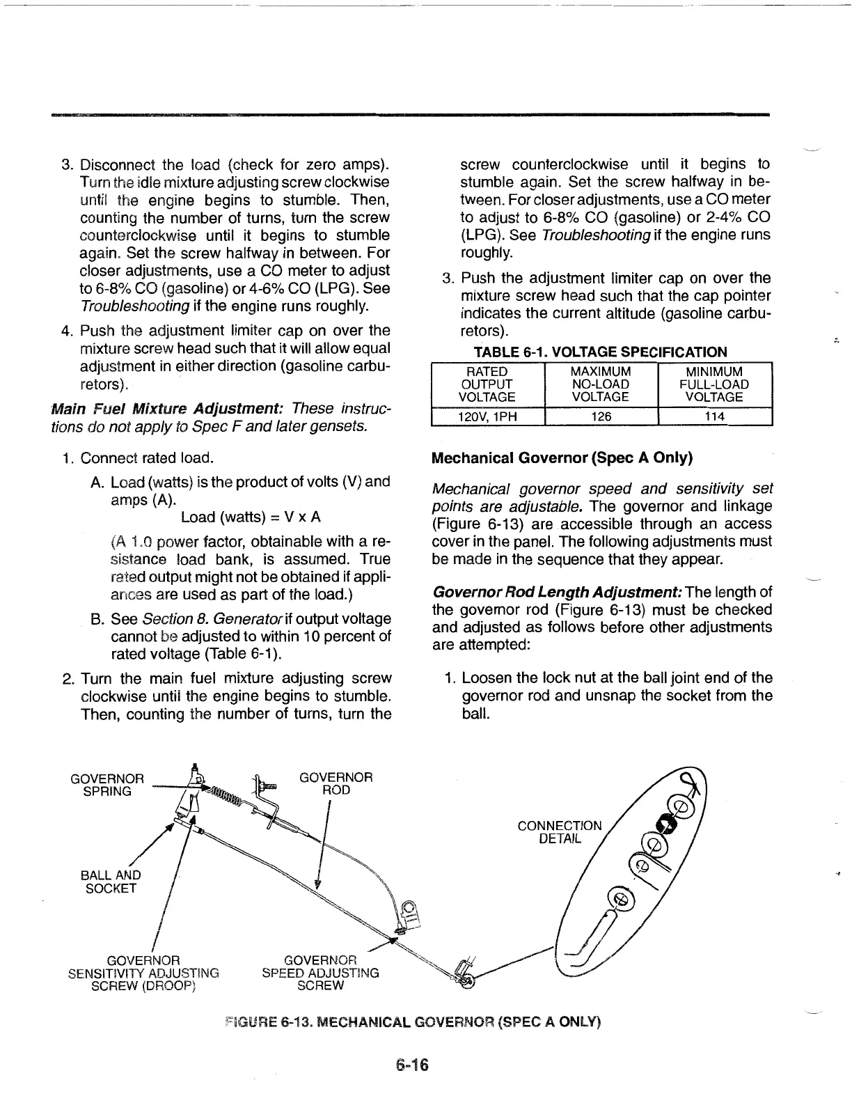
Mechanical
Governor
(Spec A Only)
Mechanical governor speed and sensitivity set
points are adjustable.
The governor and linkage
(Figure 6-13) are accessible through an access
cover
in
the panel. The following adjustments must
be
made
in
the sequence that they appear.
Governor
Rod
Length
Adjustment:
The length of
the governor rod (Figure 6-13) must be checked
and adjusted as follows before other adjustments
are attempted:
1.
Loosen the lock nut at the ball joint end of the
governor rod and unsnap the socket from the
ball.
~'~
GOVERNOR
""'""
SPEED ADJUSTING .
SCREW
:::1GURE
6-13.
MECHANICAL
GOVERNOR (SPEC A ONLY)
6-16
 Loading...