Choke Replacement: If the choke does not open,
remove the protective plastic cover and check the
heating element.
The
heating element cover should
heat up after a few minutes
of
operation. If the ele-
ment cover remains cool, start the set, then use an
AC voltmeter
to
check the terminals on the cover. If
roughly
20
VAC is not present, check for opens
or
shorts in the control wiring.
If voltage is present, stop the set and remove the
heating element cover. Inspect the heating element
and replace it if burned
out
or
broken. Also inspect
the bi-metal coil and replace it if it is damaged or
binding
in
the housing.
When installing a new bi-metal strip, maintain the
original direction
ofthe
spiral {see Figure 6-23). The
outer tab must point in a clockwise direction. Make
sure that the coil sets squarely in the housing, and
that the inner end
of
the coil engages the slot in the
choke shaft.
The
slotted tang on the element cover
must engage
the
bi-metal strip.
OUTER TAB
FIGURE 6-23. BI-METAL COIL
Choke
Pulloff
Diaphragm
Adjustment:
The
choke pulloff diaphragm partially opens the choke
plate after engine startup.
This
inhibits flooding, and
promotes smooth engine operation as the set
warms up.
1. Remove the air cleaner assembly as described
in Air Cleaner Assembly in this section, to ac-
cess the choke plate.
6-26
2. Disconnect the diaphragm hose from the in-
take manifold. Apply 4-18 inch ( 13.5-60.8 kPa)
Hg vacuum to the diaphragm.
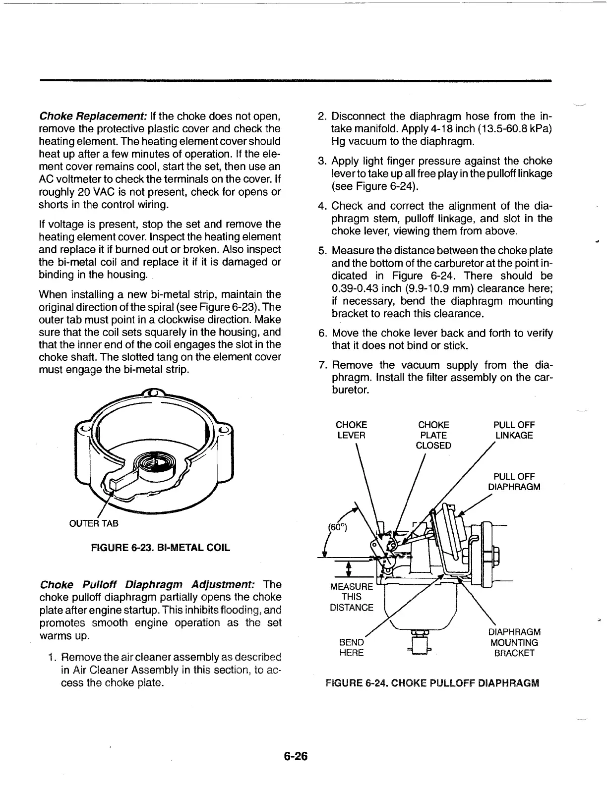
3.
Apply light finger pressure against the choke
lever
to
take up all free play
in
the pull off linkage
(see Figure 6-24).
4.
Check
and correct the alignment
of
the dia-
phragm stem, pulloff linkage, and slot in the
choke lever, viewing them from above.
5.
Measure the distance between the choke plate
and the bottom of the carburetor
at
the point in-
dicated in Figure 6-24. There should be
0.39-0.43 inch (9.9-1 0.9 mm) clearance here;
if necessary, bend the diaphragm mounting
bracket
to
reach this clearance.
6.
Move the choke lever back and forth
to
verify
that it does not bind
or
stick.
7. Remove the vacuum supply from the dia-
phragm. Install the filter assembly on the car-
buretor.
CHOKE
LEVER
PULL OFF
LINKAGE
DIAPHRAGM
MOUNTING
BRACKET
FIGURE 6-24. CHOKE PULLOFF DIAPHRAGM
 Loading...