Choke Assembly
(Beginning Spec D Gasoline)
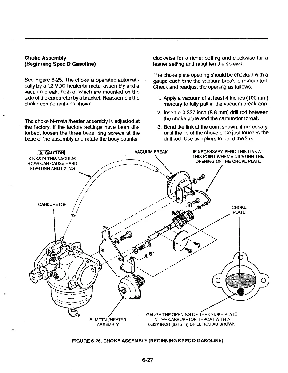
See Figure 6-25. The choke is operated automati-
cally by a 12 VDC heater/bi-metal assembly and a
vacuum break, both
of
which are mounted on the
side of the carburetor by a bracket. Reassemble the
choke components as shown.
The choke bi-metal/heater assembly is adjusted at
the factory. If the factory settings have been dis-
turbed, loosen the three bezel ring screws at the
base of the assembly and rotate the body counter-
JA
CAUTIONJ
KINKS IN THIS VACUUM
HOSE
CAN CAUSE HARD
STARTING
AND
IDLING
CARBURETOR
BI-METAL/HEATER
ASSEMBLY
clockwise for a richer setting and clockwise for a
leaner setting and retighten the screws.
The choke plate opening should be checked with a
gauge each time the vacuum break is remounted.
Check and readjust the opening
as
follows:
1.
Apply a vacuum of
at
least 4 inches
(1
00 mm)
mercury to fully pull in the vacuum break arm.
2.
Insert a 0.337 inch (8.6 mm) drill rod between
the choke plate and the carburetor throat.
3.
Bend the link at the point shown, if necessary,
until the lip of the choke plate just touches the
drill rod. Use two pliers to bend the link.
IF NECESSARY, BEND THIS LINK AT
THIS POINT
WHEN
ADJUSTING
THE
OPENING
OF
THE CHOKE PLATE
~/
CHOKE
PLATE
GAUGE THE OPENING
OF
THE CHOKE PLATE
IN THE CARBURETOR THROAT WITH A
0.337 INCH {8.6
mm) DRILL ROD AS SHOWN
FIGURE 6-25. CHOKE ASSEMBLY (BEGINNING SPEC D GASOLINE)
6-27
 Loading...