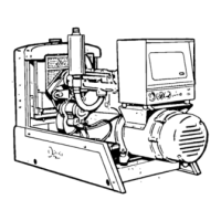
INSTALLATION
GENERAL
Installations must be considered individually. Use
these instructions as a general guide. Meet
regulations of local building codes, fire ordinances,
etc., which may affect installation details. See Figure
4.
Installation points to consider include:
1.
Level mounting surface.
2.
Adequate cooling air.
3. Adequate fresh induction air.
4.
Discharge of circulated air.
5. Discharge of exhaust gases.
6. Electrical connections.
7. Fuel connections.
8. Accessibility for operation and servicing.
9. Vibration isolation.
10.
Noise levels.
LOCATION
Provide a location that is protected from the weather
and is dry, clean, dust free and well ventilated. If
practical,
install inside a heated building for protec-
tion from extremes in weather conditions.
The air discharge side of set requires 3 inches
clearance from wall to permit set to rock on its
mounts; at least 24 inches clearance is required
around all other sides for service accessibility.
MOUNTING
A permanent installation needs a sturdy, level moun-
ting base of concrete, heavy wood or structural steel,
preferably raised to aid oil changing and operation.
Set may be bolted in position if
desired.
Allow at least
24 inch clearance on all sides of the set for
con-
venience in servicing.
Mobile applications (as in trucks or trailers) must be
securely bolted down to prevent shifting in transit.
Extra support for the vehicle flooring may be
necessary. On all installations, carefully assemble the
mounting cushions, washers and spacer bushing.
The spacer bushing prevents compression of the
snubber (upper rubber cushion). Place the cushions
under the engine and generator mounting feet, using
cushions with higher number (part number is shown
on cushion) on generator (heavier) end. Space the
7/16-inch diameter mounting bolts in floor or base
with distances between hole centers as follows:
Engine end — 11 inches; generator end — 10-1/2
inches; and engine-to-generator — 21 inches.
Be sure there is at least
1/2-inch
clearance
between oil filter and end of mounting bolt to
avoid puncturing the filter.
VENTILATION
Generator sets create a considerable amount of heat
which must be removed by proper ventilation. Out-
door installation can rely on natural air circulation,
but mobile and indoor installations need properly
sized and positioned vents for the required air flow.
See Specifications for air requirements at 1800 rpm.
Cooling air travels from the rear of the set to the front
end.
Locate the room or compartment air inlet where
most convenient, preferably to the rear of the set. The
inlet opening should be at least as large as the
radiator area.
Engine heat is removed by a pusher fan which blows
cooling air out through the front of the radiator. The
cooling air outlet should be directly in front of the
radiator and as close as is practical. The opening size
should be at least as large as the radiator area. A duct
of canvas or sheet metal may be used between the
radiator and the air outlet opening. Ducts prevent
recirculation of heated air.
Generator cooling air is discharged from the engine-
to-generator-adapter on the left side of the engine.
In cold weather a means of restricting the air flow can
be provided to keep the room or compartment
temperature at a normal point.
On city water cooled sets, the conventional radiator is
not used and a constant water flow cools the engine.
Ventilation is seldom a problem, but sufficient air
movement and fresh air must be available to properly
cool the generator and support combustion in the
engine. For small compartments, a duct larger than
the generator outlet opening is recommended to
remove heated air from the generator to the outside.
Limit bends and use radius type elbows where
needed.
A large, well ventilated compartment or room
does not require a hot air duct. Water cooled exhaust
manifolds are recommended.
CITY
WATER
COOLING
(OPTIONAL)
Connections on the engine are 3/8-inch pipe. A
solenoid shut-off valve and a lockshield supply valve
are furnished but not installed. The solenoid valve is
coordinated with the engine control to shut off the
water supply when set is not in use.
The lock shield valve is manually adjusted to control
water rate-of-flow for proper cooling with a minimum
flow of water. Final adjustment should be made under
the maximum load the set will carry with the engine
thoroughly warmed up and water temperature
stabilized.
Refer to Specifications for water flow data.

 Loading...