HEAT
EXCHANGER
COOLING
(OP-
TIONAL)
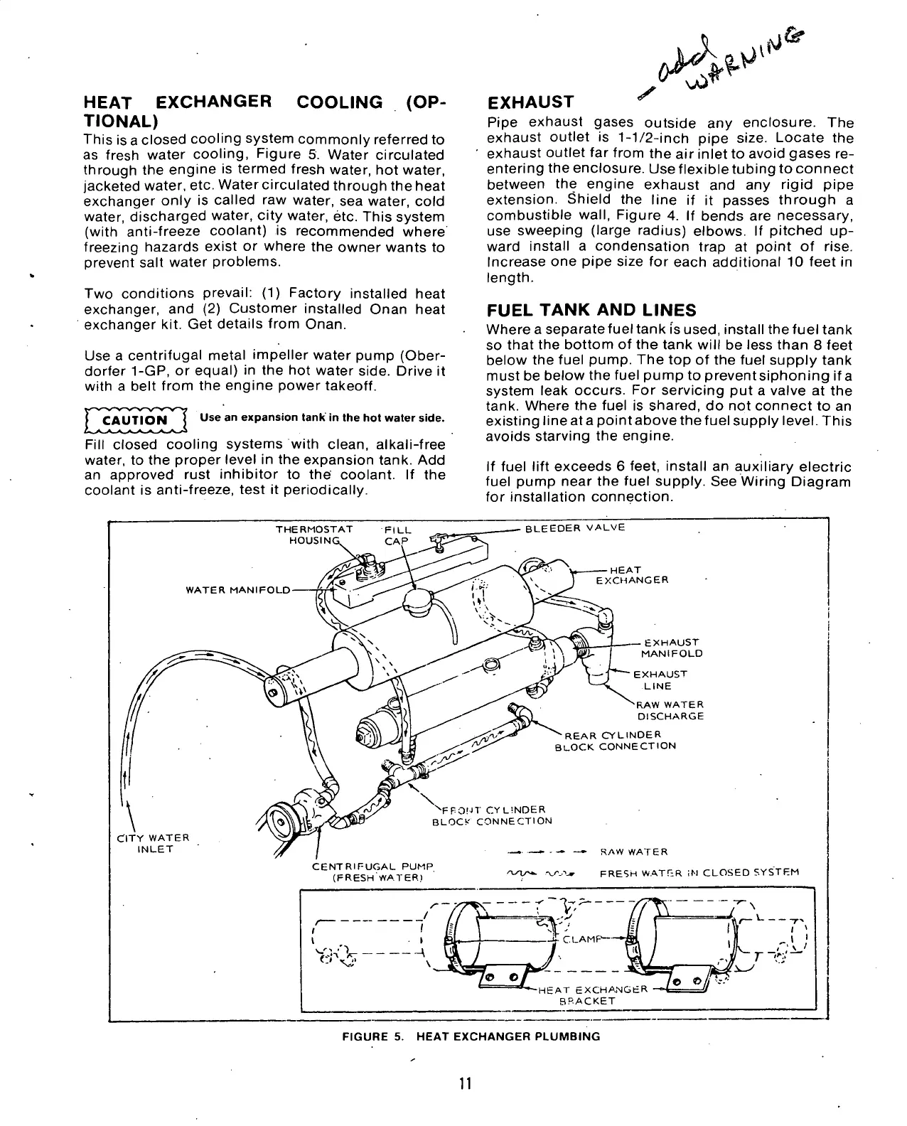
This is a closed cooling system commonly referred to
as fresh water cooling, Figure 5. Water circulated
through the engine is termed fresh water, hot water,
jacketed water, etc. Water circulated through the heat
exchanger only is called raw water, sea water, cold
water, discharged water, city water, etc. This system
(with anti-freeze coolant) is recommended where
freezing hazards exist or where the owner wants to
prevent salt water problems.
Two conditions prevail: (1) Factory installed heat
exchanger, and (2) Customer installed Onan heat
exchanger kit. Get details from Onan.
Use a centrifugal metal impeller water pump (Ober-
dorfer 1-GP, or equal) in the hot water side. Drive it
with a belt from the engine power takeoff.
Use an expansion tank in the hot water side.
Fill closed cooling systems with clean, alkali-free
water, to the proper level in the expansion tank. Add
an approved rust inhibitor to the coolant. If the
coolant is anti-freeze, test it periodically.
EXHAUST
Pipe exhaust gases outside any enclosure. The
exhaust outlet is
1-1/2-inch
pipe size. Locate the
exhaust outlet far from the air inlet to avoid gases re-
entering the enclosure. Use flexibletubing to connect
between the engine exhaust and any rigid pipe
extension.
Shield the line if it passes through a
combustible
wall,
Figure 4. If bends are necessary,
use sweeping (large radius) elbows. If pitched up-
ward install a condensation trap at point of rise.
Increase one pipe size for each additional 10 feet in
length.
FUEL
TANK AND
LINES
Where a separate fuel tank fs used, install the fuel tank
so that the bottom of the tank will be less than 8 feet
below the fuel pump. The top of the fuel supply tank
must be below the fuel pump to preventsiphoning ifa
system leak occurs. For servicing put a valve at the
tank. Where the fuel is shared, do not connect to an
existing line at a point above the fuel supply level. This
avoids starving the engine.
If fuel lift exceeds 6 feet, install an auxiliary electric
fuel pump near the fuel supply. See Wiring Diagram
for installation connection.
THERMOSTAT
HOUSIN
BLEEDER VALVE
WATER MANIFOLD-
EXCHANGER
EXHAUST
MANIFOLD
\
CITY WATER
INLET
RAW WATER
DISCHARGE
REAR CYLINDER
BLOCK CONNECTION
N
FFONT CYLINDER
BLOCS'
CONNECTION
CENTRIFUGAL PUMP
(FRESH WATER)
_ - RAW WATER
'T-T^
--xyvw FRESH WAT fi
R
iM CLOSED SYSTEM
/— /
1 1
l i Bl
siji'V * \3
l i Bl
siji'V * \3
\)
/ nfl j
l i Bl
siji'V * \3
Of
"^"-HEAT EXCHANGER
BRACKET
EE? Ifo^iS
Of
"^"-HEAT EXCHANGER
BRACKET
FIGURE 5. HEAT EXCHANGER PLUMBING
11

 Loading...

