Use approved flexible fuel line next to the engine.
Diesel engines require a fuel supply line and a
separate fuel return line. Install the fuel supply line
from the supply tank to the inverted flare male elbow
mounted in the inlet of the fuel pump. Install the fuel
return line from the injection pump bleeder valve to
the supply tank, Figure 6.
LOAD
SEN.
NOZZLES-
FUEL RETURN
LINES (SHADED)
CONNECT FUEL
RETURN LINE
HERE (FLEXIBLE)
INJECTION
PUMP
FIGURE 6. FUEL SYSTEM
Do not use galvanized lines, fittings, or fuel tanks in
the fuel system. Carefully clean all fuel system
components before putting the set into operation.
Any dirt or contamination may cause major damage
to the fuel injection system.
OIL
DRAIN
Extend to suit installation. Oil base has a 1/2 inch pipe
tapped hole.
ELECTRICAL
CONNECTIONS
The nameplate on the generator set shows the
electrical output rating of the generator in watts, volts,
and hertz. The wiring diagram, shipped with the
generator set, shows the electrical circuits and
con-
nections needed during installation.
All electrical connections should be done by a
qualified serviceman or electrician to meet the elec-
trical code requirements in your area.
LOAD
WIRES
The control box (junction box) has knock out sec-
tions to accommodate load wires. Use flexible
con-
duit and stranded load wires near the set to absorb
vibration..
Use sufficiently large insulated wires. Strip
insulation from wire ends as necessary for clean
connections. Connect each load wire to the proper
generator output lead inside the set box. Insulate bare
ends of ungrounded wires. Use bolt provided on
control box to connect the generatorground lead and
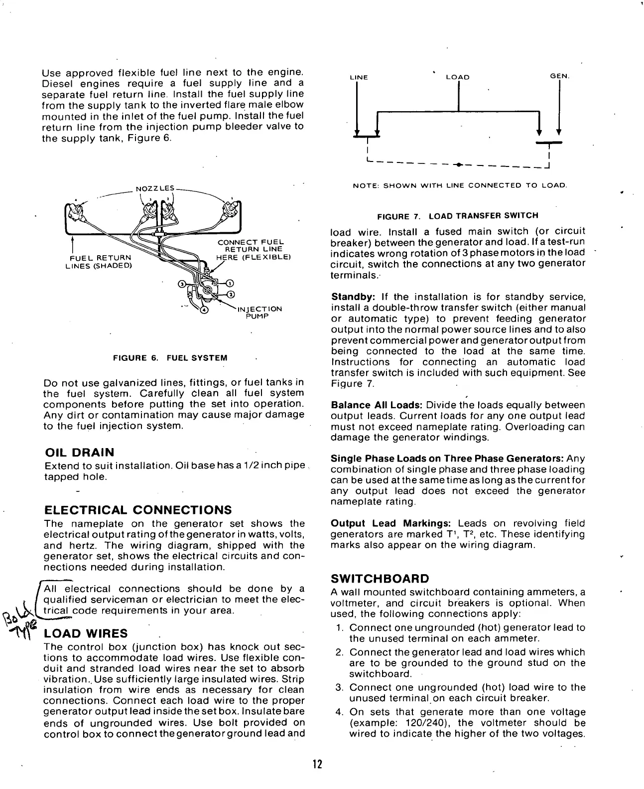
NOTE:
SHOWN WITH LINE CONNECTED TO LOAD.
FIGURE 7. LOAD TRANSFER SWITCH
load wire. Install a fused main switch (or circuit
breaker) between the generator and
load.
If a test-run
indicates wrong rotation of 3 phase motors in the load
circuit, switch the connections at any two generator
terminals.
Standby: If the installation is for standby service,
install a double-throw transfer switch (either manual
or automatic type) to prevent feeding generator
output into the normal power source lines and to also
prevent commercial power and generator output from
being connected to the load at the same time.
Instructions for connecting an automatic load
transfer switch is included with such equipment. See
Figure 7.
Balance All Loads: Divide the loads equally between
output leads. Current loads for any one output lead
must not exceed nameplate rating. Overloading can
damage the generator windings.
Single Phase Loads on Three Phase Generators: Any
combination of single phase and three phase loading
can be used at the same time as long as the current for
any output lead does not exceed the generator
nameplate rating.
Output Lead Markings: Leads on revolving field
generators are marked T
1
, T
2
, etc. These identifying
marks also appear on the wiring diagram.
SWITCHBOARD
A wall mounted switchboard containing ammeters, a
voltmeter, and circuit breakers is optional. When
used,
the following connections apply:
1.
Connect one ungrounded (hot) generator lead to
the unused terminal on each ammeter.
2.
Connect the generator lead and load wires which
are to be grounded to the ground stud on the
switchboard.
3. Connect one ungrounded (hot) load wire to the
unused terminal on each circuit breaker.
4.
On sets that generate more than one voltage
(example: 120/240), the voltmeter should be
wired to indicate the higher of the two voltages.
12

 Loading...

