windings, is fed to the voltage regulator as a reference
voltage for maintaining the generator output voltage.
The AC reference voltage is converted to DC by a
silicon controlled rectifier bridge on the voltage
regulator printed circuit board and fed into the exciter
field windings. The exciter armature produces three-
phase AC voltage that is converted to DC by the
rotating rectifier assembly. The resultant DC voltage
excites the generator rotor winding to produce the
stator output voltage for the AC
load.
VOLTAGE REGULATOR
LOCATION
WIO
0
VR2I
®
T2I
CMR2I
REFERENCE
VOLTAGE
TRANSFORMER
COMMUTATING
REACTOR
TB2I 9
NOTE:
FIELD
BREAKER IS
MOUNTED ON
PANEL
FIGURE 2.. VOLTAGE REGULATOR
The generator rotor also produces AC voltage (19 to
21 volts) in the charging winding of the stator which is
converted to direct current for battery charging.
VOLTAGE
REGULATOR
(Spec
AA)
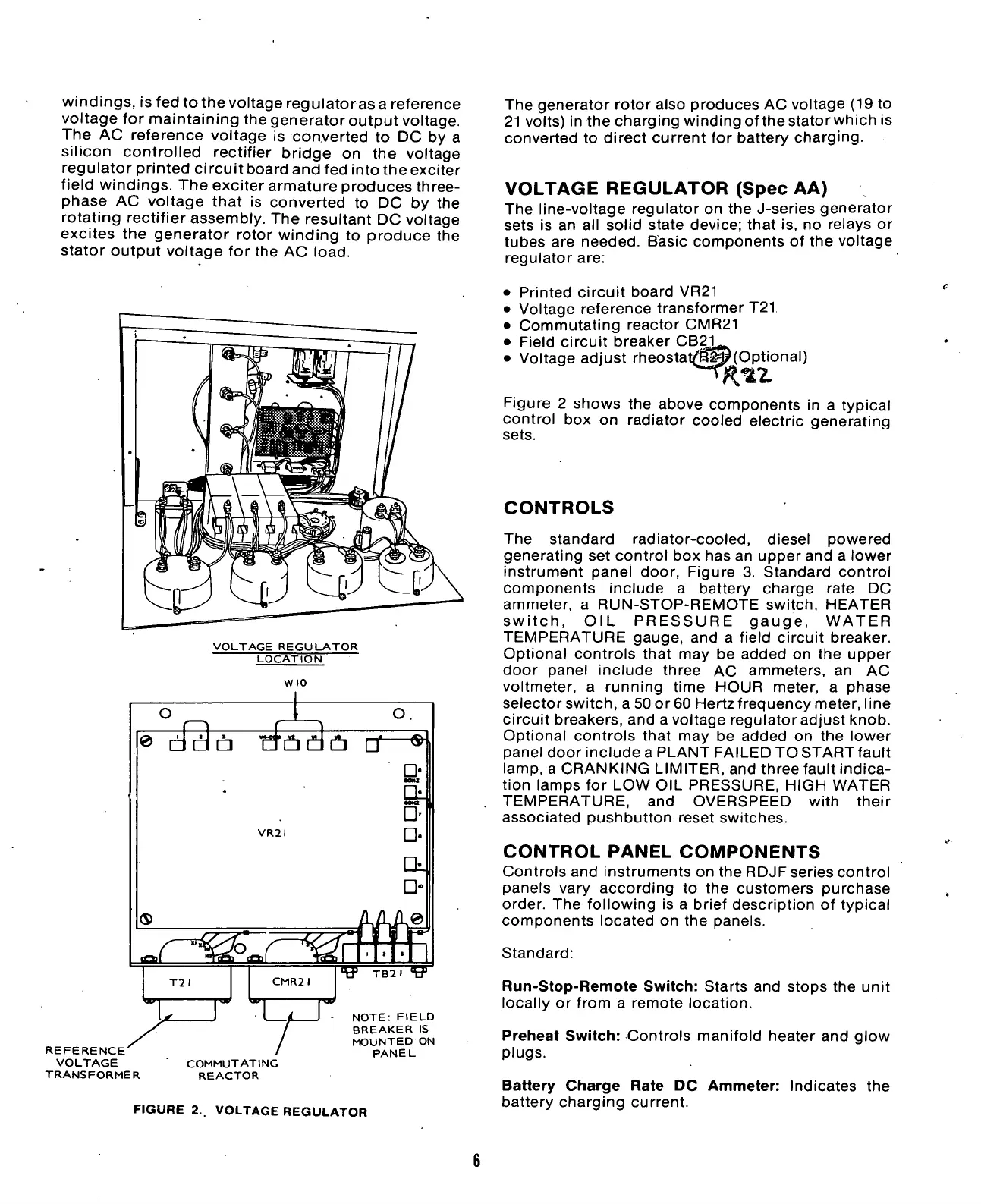
The line-voltage regulator on the J-series generator
sets is an all solid state device; that is, no relays or
tubes are needed. Basic components of the voltage
regulator are:
• Printed circuit board VR21
• Voltage reference transformer T21
• Commutating reactor CMR21
• Field circuit breaker CBg^
• Voltage adjust rheostat(iEip(Optional)
Figure 2 shows the above components in a typical
control box on radiator cooled electric generating
sets.
CONTROLS
The standard radiator-cooled, diesel powered
generating set control box has an upper and a lower
instrument panel door, Figure 3. Standard control
components include a battery charge rate DC
ammeter, a RUN-STOP-REMOTE switch, HEATER
switch,
OIL PRESSURE gauge, WATER
TEMPERATURE gauge, and a field circuit breaker.
Optional controls that may be added on the upper
door panel include three AC ammeters, an AC
voltmeter, a running time HOUR meter, a phase
selectorswitch, a 50or60 Hertz frequency meter, line
circuit breakers, and a voltage regulator adjust knob.
Optional controls that may be added on the lower
panel door include a PLANT FAILED TO START fault
lamp,
a CRANKING LIMITER, and three fault indica-
tion lamps for LOW OIL PRESSURE, HIGH WATER
TEMPERATURE, and OVERSPEED with their
associated pushbutton reset switches.
CONTROL
PANEL
COMPONENTS
Controls and instruments on the RDJF series control
panels vary according to the customers purchase
order. The following is a brief description of typical
components located on the panels.
Standard:
Run-Stop-Remote Switch: Starts and stops the unit
locally or from a remote location.
Preheat Switch: Controls manifold heater and glow
plugs.
Battery Charge Rate DC Ammeter: Indicates the
battery charging current.

 Loading...

