AC
AMMETERS
WATE
HEATER SWITCH
RUN-STOP SWITCH
DC AMMETER
TEMPERATURE GAUGE
AC
VOLTMETER
PHASE
SELECTOR
SWITCH
FREQUENCY
METER
VOLTAGE
ADJUST
RHEOSTAT
INDICATORS
RESET
BUTTONS
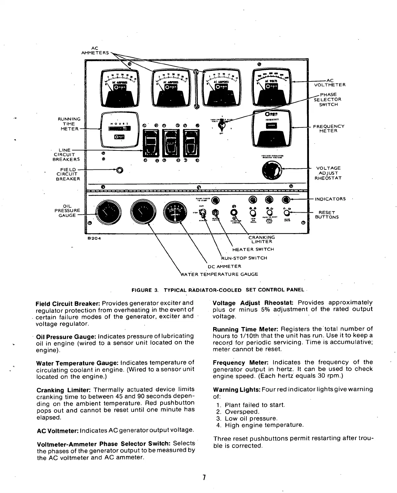
FIGURE
3.
TYPICAL RADIATOR-COOLED SET CONTROL PANEL
Field Circuit Breaker: Provides generator exciter and
regulator protection from overheating
in
the event
of
certain failure modes
of
the
generator, exciter
and
voltage regulator.
Oil Pressure Gauge: Indicates pressure
of
lubricating
oil
in
engine (wired
to a
sensor unit located
on the
engine).
Water Temperature Gauge: Indicates temperature
of
circulating coolant
in
engine. (Wired
to
a sensor unit
located
on the
engine.)
Cranking Limiter: Thermally actuated device limits
cranking time
to
between
45
and
90
seconds depen-
ding
on
the
ambient temperature.
Red
pushbutton
pops
out and
cannot
be
reset until
one
minute
has
elapsed.
AC Voltmeter: Indicates AC generator output voltage.
Voltmeter-Ammeter Phase Selector Switch: Selects
the phases
of
the generator output
to
be measured
by
the
AC
voltmeter and
AC
ammeter.
Voltage Adjust Rheostat: Provides approximately
plus
or
minus
5%
adjustment
of
the
rated output
voltage.
Running Time Meter: Registers
the
total number
of
hours
to
1/10th
that
the
unit has run. Use itto keep
a
record
for
periodic servicing. Time
is
accumulative;
meter cannot
be
reset.
Frequency Meter: Indicates
the
frequency
of the
generator output
in
hertz.
It
can
be
used
to
check
engine speed. (Each hertz equals
30 rpm.)
Warning Lights: Fourred indicatorlightsgivewarning
of:
1.
Plant failed
to
start.
2.
Overspeed.
3.
Low oil
pressure.
4.
High engine temperature.
Three reset pushbuttons permit restarting after
trou-
ble
is
corrected.

 Loading...

