8. Disconnect battery and follow standard battery
storage procedure.
9. Provide a suitable cover for the entire unit.
Returning a Unit to Service.
1.
Remove cover and all protective wrapping.
Remove plug from exhaust outlet.
2.
Check warning tag on oil base and verify that oil
viscosity is still correct for existing ambient
temperature.
3. Clean and check battery. Measure specific gravity
(1.260 at 77° F [25°C] ) and verify level to be at
split
ring.
If specific gravity is few, charge until
correct value is obtained. If level is low, add
distilled water and charge until specific gravity is
correct. DO NOT OVERCHARGE.
~k Do not smoke while servicing
J batteries. Explosive gases are emitted
WARNING
from batteries in operation. Ignition of these gases can cause
severe personal injury.
4.
Check that fuel injectors and fuel lines are secure,
correctly torqued.
5. Check coolant level, adjust if necessary.
6. Connect batteries.
7. Verify that no loads are connected to generator.
8. Start engine.
After engine has started, excessive blue smoke will be
exhausted until the rust inhibitor or oil has burned away.
9. After start, apply load to at least 50 percent of
rated capacity.
10.
Check all gauges to be reading correctly. Unit is.
ready for service.
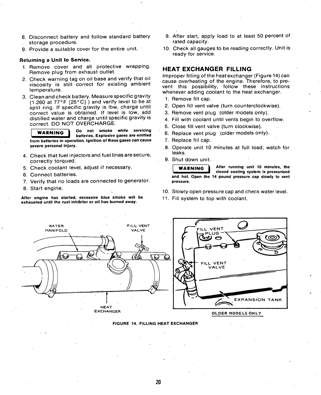
HEAT
EXCHANGER
FILLING
Improper filling of the heat exchanger (Figure 14) can
cause overheating of the engine. Therefore, to pre-
vent this possibility, follow these instructions
whenever adding coolant to the heat exchanger.
1.
Remove fill cap.
2.
Open fill vent valve (turn counterclockwise).
3. Remove vent plug (older models only).
4.
Fill with coolant until vents begin to overflow.
5. Close fill vent valve (turn clockwise).
6. Replace vent plug (older models only).
7. Replace fill cap.
8. Operate unit 10 minutes at full
load;
watch for
leaks.
9. Shut down unit.
WARNING
After running unit 10 minutes, the
closed cooling system is pressurized
and hot. Open the 14 pound pressure cap slowly to vent
pressure.
10.
Slowly open pressure cap and check water level.
11.
Fill system to top with coolant.
WATER
MANIFOLD
HEAT
EXCHANGER
EXPANSION TANK
OLDER MODELS ONLY
FIGURE 14. FILLING HEAT EXCHANGER
20

 Loading...

