1500 North Belcher Road, Clearwater, FL 33765 • Tel (727) 447-6140 • Fax (727) 442-5699 • sales@onicon.com
Turbine Flow Meter Manual 05/13 - 0721-1 / 13518 Page 15
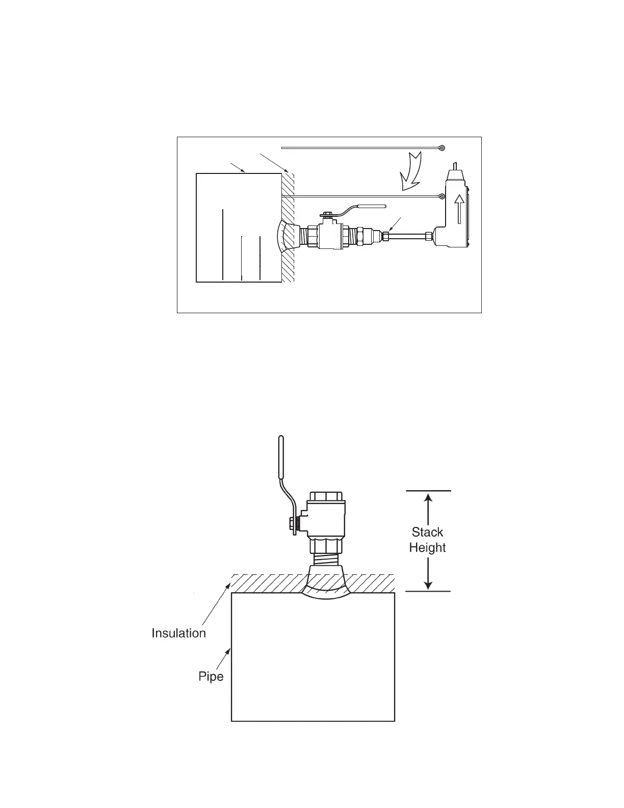
3.3.5 Conrming the Stack Height
ONICON insertion ow meter stem lengths vary according to the pipe diameter and the
height of the installation hardware stack. ONICON records the stack height dimension
provided by the customer at the time of order entry, and the information is used to size the
stem. This dimension is shown on the laminated insertion depth gage tag attached to the
meter.
Prior to installing the meter, conrm that the stack height recorded on the tag is close to
the actual stack height. Flow meter stems are intentionally over sized to allow for
variations of at least 2” in the stack height. Contact ONICON prior to installation if there
is any question regarding stack height or stem length. This will allow ONICON to offer
you credit for your meter if you decide to exchange the meter for one with a different stem
length. Returns may be subject to a restocking fee.
Depth Gage
1) Pierce insulation until
gage tip touches pipe.
Lock Nut
READ OTHER SIDE OF THIS TAG BEFORE INSTALLING METER
DO NOT USE FOR
ANY OTHER METER
Insulation
Pipe
2) Insert flow meter until
bottom of electronics case
touches eye of depth gage.
3) Confirm arrow is
aligned with flow
and tighten lock nut.
GAGE LENGTH 10.937"
STACK HEIGHT 8.5”
FOR S/N #250791
Flow Direction
THIS GAGE WAS CUT TO LENGTH
FOR THIS METER AND PIPE SIZE ONLY.
DO NOT USE FOR ANY OTHER METER OR OTHER PIPE SIZE.
This is not a complete installation procedure. Please see
the Installation and Adjustment Guide for complete
instructions and important safety information.
1500 North Belcher Road, Clearwater, Florida 33765 Tel (727) 447-61402057C-4
12-12
 Loading...


