1500 North Belcher Road, Clearwater, FL 33765 • Tel (727) 447-6140 • Fax (727) 442-5699 • sales@onicon.com
Turbine Flow Meter Manual 05/13 - 0721-1 / 13518 Page 4
SECTION 1.0: INTRODUCTION
We, at ONICON Incorporated, would like to thank you for purchasing our quality, U.S. made, Turbine
Flow Meter. As our valued customer, our commitment to you is to provide fast reliable service and
assistance, while continuing to offer you new products to meet your growing ow measurement needs.
1.1 PURPOSE OF THIS GUIDE
We have written this guide to provide the persons responsible for the installation, operation and
maintenance of your turbine ow meter with the most specic equipment information they will
need. This is NOT an electrical or plumbing trade manual.
WARNING
Please do not permit any persons to install, operate or maintain this equipment unless they have a
complete knowledge of their trade skills and are competent to work on high pressure hot and cold
water systems, according to their individual trades. Death or permanent injury may result from
accidents with these systems.
This guide is the basic reference tool for all ONICON Turbine Flow Meters. If you have not
purchased all of the options, there will be references in this manual which are not applicable to
your meter(s).
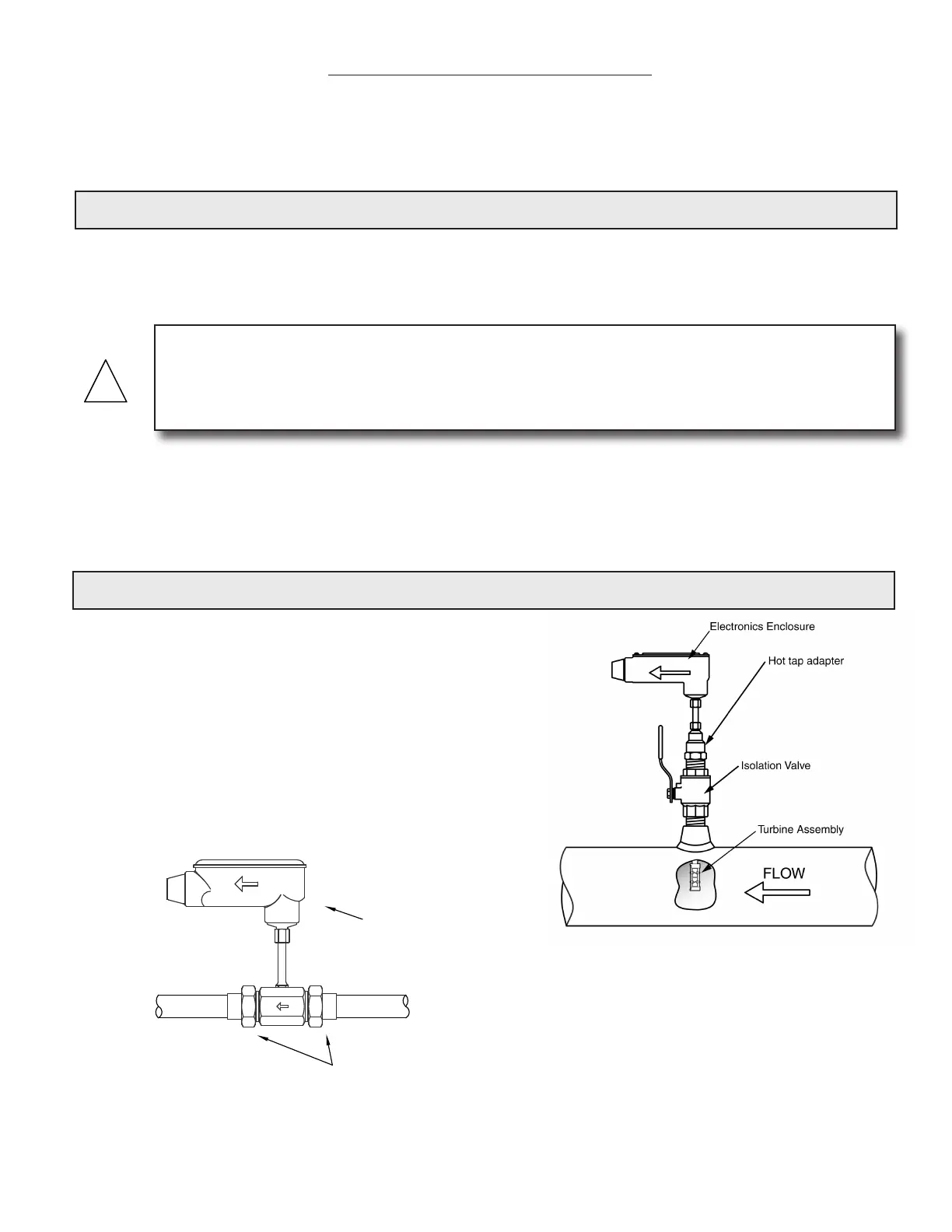
1.2 TYPICAL TURBINE FLOW METERS
ONICON’s Turbine Flow Meters measure the velocity
of owing liquids by counting the frequency at
which the blades of a rotating turbine pass a xed
electrode. Circuitry within the ow meter electronics
enclosure then converts the rotational rate to digital
and/or analog signals which are transmitted via
a connecting cable to any of ONICON’s display
devices, BTU meters and/or a data acquisition
system.
Sweat or NPT
Process Connections
Electronics Enclosure
Inline Meter
Insertion Meter
 Loading...


