1500 North Belcher Road, Clearwater, FL 33765 • Tel (727) 447-6140 • Fax (727) 442-5699 • sales@onicon.com
Turbine Flow Meter Manual 05/13 - 0721-1 / 13518 Page 20
CAUTION
Do not attempt to make any connections inside the electronics enclosure, or to remove factory
installed cable, strain relief or conduit tting. Damage resulting from these actions will not be
covered under warranty.
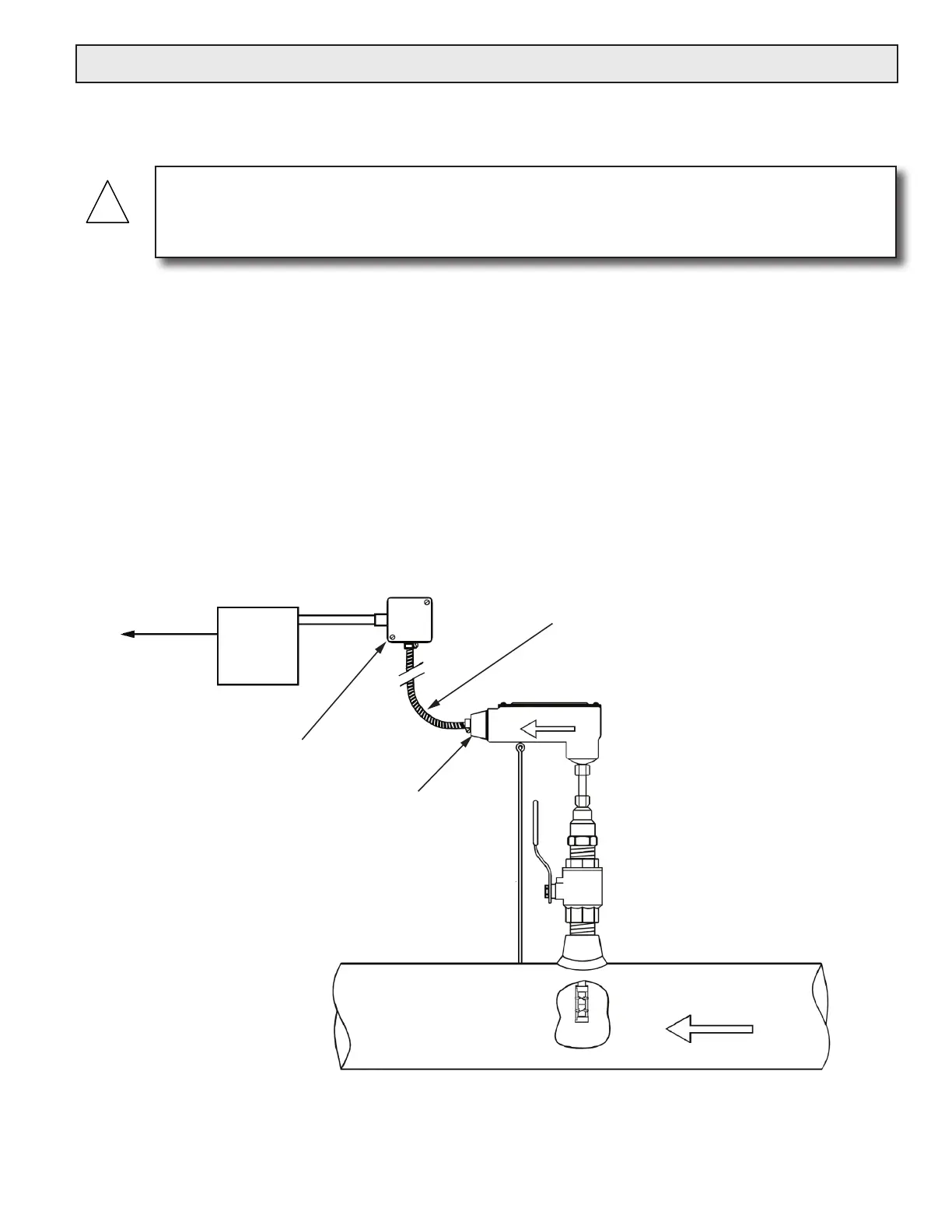
Output signal(s)
to control
system
(if ordered)
ONICON
Display or
BTU Meter
(Optional)
Connect factory wires
to field wires in appropriate
junction box.
Leave sufficient slack in conduit
and cable to allow the meter to be
removed without disconnecting wires.
½” FNPT
conduit connection
FLOW
3.7 WIRING CONNECTIONS
Make connections to the 10’ cable, which is supplied by ONICON and is pre-wired to the circuit
board.
The most common cause of electronic failures are miswired connections. If you are adding
additional cable, please record any substitution of wire colors. If additional cable is purchased
from ONICON, the color code can be maintained. Cable from other sources will most likely have a
different set of colors. Please refer to Appendix A for wiring diagrams and factory color codes.
Only qualied service personnel should make connections between the ow meter and the user’s
external equipment. Any misapplication of power and/or ground can result in improper operation
or damage to the ow meter circuitry, and to any externally connected equipment.
 Loading...


